Download
1 / 51
580 likes | 864 Vues
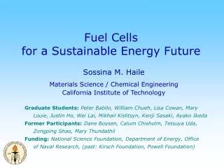
Fuel Cells for a Sustainable Energy Future. Sossina M. Haile Materials Science / Chemical Engineering California Institute of Technology. Graduate Students: Peter Babilo, William Chueh , Lisa Cowan, Mary Louie, Justin Ho, Wei Lai, Mikhail Kislitsyn, Kenji Sasaki, Ayako Ikeda

E N D
Fuel Cellsfor a Sustainable Energy Future Sossina M. Haile Materials Science / Chemical Engineering California Institute of Technology Graduate Students:Peter Babilo,William Chueh, Lisa Cowan, Mary Louie, Justin Ho, Wei Lai, Mikhail Kislitsyn, Kenji Sasaki, Ayako Ikeda Former Participants:Dane Boysen, Calum Chisholm, Tetsuya Uda, Zongping Shao, Mary Thundathil Funding:National Science Foundation, Department of Energy, Office of Naval Research, (past: Kirsch Foundation, Powell Foundation)
Contents • The Problem of Energy • Growing consumption • Consequences • Sustainable energy resources • Fuel Cell Technology Overview • Principle of operation • Types of fuel cells and their characteristics • Recent (Caltech) Advances • Too many to cover…
The Problem of Energy • The Problem • Diminishing supply? • Resources in unfriendly locations? • Environmental damage? • The Solution • Adequate domestic supply • Environmentally benign • Conveniently transported • Conveniently used
World Energy Consumption 264 8.4 211 6.7 158 5.0 Equivalent Power (TW, 1012) Exa Joules (1018) 106 3.3 52 1.7 0 0 (annual) Source: US Energy Information Agency 1999 totals: 400 Q-Btu, 422 EJ, 13TW 2020 projections: 630 Q-Btu, 665 EJ, 21TW 90% fossil
Fossil Fuel Supplies 400 yrs Source: US Energy Information Agency Rsv = Reserves (90%) Rsc = Resources (50%) 56-77 287-345
US Energy Imports/Exports: 1949-2004 1957: Net Importer Source: US Energy Information Agency Imports Exports 35 6 Total 30 5 25 4 Total 20 Quad BTU Coal 3 Quad BTU 15 2 10 Petroleum 1 5 Petroleum 0 0 1950 1960 1970 1980 1990 2000 1950 1960 1970 1980 1990 2000 • 65% of known petroleum reserves in Middle East • 3% of reserves in USA, but 25% of world consumption Net 35 30 25 20 Quad BTU 15 10 5 0 1950 1960 1970 1980 1990 2000
Environmental Outlook Global CO2 levels 2004: 378 ppm Projections: 500-700 ppm by 2020 • Anthropogenic • Fossil fuel (75%) • Land use (25%) Industrial Revolution Source: Oak Ridge National Laboratory
Environmental Outlook CO2 (ppmv) 325 300 275 CO2 in 2004: 378 ppmv CH4 (ppmv) 250 800 -- CO2 -- CH4 --T 225 + 4 700 200 0 T relative to present (°C) 175 600 - 4 500 400 - 8 300 100 400 200 300 0 Thousands of years before present (Ky BP) Intergovernmental Panel on Climate Change, 2001; http://www.ipcc.ch N. Oreskes, Science 306, 1686, 2004; D. A. Stainforth et al, Nature 433, 403, 2005
Supply Fossil energy sufficient for world demand into the forseeable future High geopolitical risk Rising costs Environmental Impact Target Stabilize CO2 at 550 ppm By 2050 Requires 20 TW carbon-free power One 1-GW power plant daily from now until then Energy Outlook Urgency • Transport of CO2 or heat into deep oceans: • 400-1000 years; CO2 build-up is cummulative • Must make dramatic changes within next few years
Solar 1.2 x 10⁵ TW at Earth surface 600 TW practical The Energy Solution The need: ~ 20 TW by 2050 Wind 2-4 TW extractable Biomass 5-7 TW gross all cultivatable land not used for food Tide/Ocean Currents 2 TW gross Hydroelectric Geothermal 4.6 TW gross 1.6 TW technically feasible 0.9 TW economically feasible 0.6 TW installed capacity 12 TW gross over land small fraction recoverable Nuclear Waste disposal Fossil with sequestration 1% / yr leakage -> lost in 100 yrs
The Energy Solution • Sufficient Domestic Supply • Coal, Nuclear, Solar • Environmentally Sustainable Supply • Solar (Nuclear?) • Suitable Carrier • Electricity? Hydrogen? Hydrocarbon? • Challenges • Convert solar (nuclear) to convenient chemical form • Efficient consumption of chemical fuel
A Sustainable Energy Cycle H2O, CO2 C-free Source Solar or nuclear power plants H2 Capture e- ??? Hydrides? Liquid H2? Batteries Storage Hydrocarbon Delivery e- Utilization H2O + CO2 Fuel cell
A Few Words on Hydrogen Fuel Cells • Hydrogen energy density • High energy content per unit mass of hydrogen • But best storage technologies are at ~ 5 wt% H2 • 5x the weight of gasoline (for same energy content) • Conventional hydrogen fuel cells require Pt • DOE target: 1 g/kW (0.75 g/hp) • 100 hp engine 75g Pt $3,169 • 93% of US Pt is imported • 80% of world reserves in one mine complex in SA • Another 15% in one mine complex in Russia • Converting US autos would double world consumption • 4 yr auto lifetime, 20% recycling out in 40 yrs
Fuel Cells: Part of the Solution? • High efficiency • low CO2 emissions • Size independent • Various applications • stationary • automotive • portable electronics • Controlled reactions • “Zero Emissions” • Operable on hydrogen • (if suitably produced) * *Can be as high as 80-90% with co-generation
Fuel Cell: Principle of Operation Anode Cathode best of batteries, combustion engines conversion device, not energy source e- H+ H2 O2 H2 2H+ + 2e- ½ O2 + 2H+ + 2e- H2O Electrolyte Overall: H2 + ½ O2 H2O
Fuel Cell Performance H2 + ½ O2 H2O 1.17 Volts (@ no current) • voltage losses • fuel cross-over • reaction kinetics • electrolyte resistance • slow mass diffusion • power = I*V • peak efficiency at low I • peak power at mid I 1.2 0.8 cross-over theoretical voltage 1.0 slow reaction kinetics 0.6 0.8 peak power Power [W / cm2] 0.6 0.4 Voltage [V] 0.4 electrolyte resistance 0.2 0.2 slow mass diffusion 0.0 0.0 0.0 0.4 0.8 1.2 1.6 Current [A / cm2 ]
Components Electrolyte (Membrane) Transport ions Block electrons, gases Electrodes Catalyze reactions Transport Ions, electrons, gases May be a composite (electro)Catalyst + Conductors + Pore former Fuel Cell Components catalyst electrodes sealant electrolyte Membrane-Electrode Assembly (MEA)
Fuel Cell Types Types differentiated by electrolyte, temperature of operation Low T H2 or MeOH; High T higher hydrocarbons (HC) Efficiency tends to as T , due to faster electrocatalysis By-products: H2O, CO2
Ambient Temperature Rapid start-up H2 or CH3OH as fuels Catalysts easily poisoned Applications Portable power Many on/off cycles Small size High Temperature Fuel flexible Very high efficiencies Long start-up Applications Stationary power Auxiliary power in portable systems Fuel Cell Choices Temperature sets operational parameters & fuel choice
Technology Status • Many, many demonstrate sites and vehicles • Stationary PAFC (200 kW) at military sites since 1995 • Stationary SOFC (100 kW) operated for 20,000 hrs • Toyota and Honda PEM FC vehicles released 2002 • DaimlerChrysler, Ford and GM, 2005; Hyundai planned • Legislation is a key driver • California zero emissions automotive standards • China set for tough ‘CAFE’ standards • Cost is a major barrier • Precious metal catalysts, fabrication, complexity • Uncertainty in future fuel infrastructure • Gasoline for how long? Hydrogen? Methanol?
Fuel Cell System Complexity Membrane electrode assembly sealant electrolyte electrodes catalyst Electrolyte System Stack
Philosophy Challenge • Limitation of fuel cell materials places severe design constraints on fuel cell systems Approach • Material modification for improved performance and system simplification • New materials discovery for next generation fuel cell systems • Novel system designs
Fuel Cell Innovations • New Electrolytes • Intermediate temperature operation • Lower the temperature below solid oxide fuel cells • Raise the temperature above polymer fuel cells • New Catalysts • Enhance reaction kinetics (improve efficiency) • Reduce susceptibility to poisons (reduce complexity) • Novel integrated designs • Dramatically improve thermal management • Utilize micromachining technologies – micro fuel cells
New Electrolytes: Solid Acids NSF & DOE Sponsored Program(past ONR support)
“PEM” Fuel Cells H(H2O)n+ H2O SO3- + (H2O)nH+ 1 nm (CF2)n Proton Exchange Membrane or Polymer Electrolyte Membrane Nafion (Dupont) • saturate with H2O • inverse micelle structure • H(H2O)n+ ion transport • High conductivity • Flexible, high strength • Requires humidification & water management • Operation below 90°C • Permeable to methanol Kreuer, J Membr Sci2 (2001) 185. Target: 120-300°C; examine inorganic H+ conductors
Solid Acids • Chemical intermediates between normal salts and normal acids: “acid salts” ½(Cs2SO4) + ½(H2SO4) CsHSO4 • Physically similar to salts • Structural disorder at ‘warm’ temperatures • Properties • Direct H+ transport • Humidity insensitive • Impermeable • Water soluble!! Brittle
Proton Transport Mechanism H Sulfate groupreorientation 10-11 seconds S O Proton transfer 10-9 seconds
Conductivity of Solid Acids • CsHSO4[Baranov, 1982] • CsHSeO4[Baranov, 1982] • (NH4)3H(SO4)2[Ramasastry, 1981] • Rb3H(SeO4)2[Pawlowski, 1988] • Cs2(HSO4)(H2PO4)[Chisholm & Haile, 2000] • b-Cs3(HSO4)2(H2PO4)[Haile et al., 1997] • K3H(SO4)2[Chisholm & Haile, 2001] Superprotonic transition But sulfates and selenates are unstable under reducing conditions…
The Good H+ transport only No electro-osmotic drag No electron transport Alcohol impermeable Humidity insensitive conductivity Stable to ~ 250ºC Inexpensive Chemically non-aggressive The Bad Known compounds are water soluble Operate at T 100ºC Insoluble analogs? Few are chemically stable The Ugly Poor processability and mechanical properties Composite membranes with inert polymers Solid Acid Properties
CsH2PO4 as a Fuel Cell Electrolyte • Expected to have chemical stability • 3CsH2PO4 + 11H2 Cs3PO4 + 3H3P + 8H2O • dG(rxn) >> 0 • But does it have high conductivity? • Does it have sufficient thermal stability? • Literature dispute • High conductivity on heating due to H2O loss • High conductivity due to transition to a cubic phase
CsH2PO4 Dehydration CsH2PO4 CsPO3 + H2O pressure detector Tc = 230 Toper = 250°C CsH2PO4 + H2O P(H2O) operation CsH2PO4 CsH2-2xPO4-x Use water partial pressure to suppress dehydration
Conductivity of CsH2PO4 0.42 eV Humidified airp[H2O] = 0.4 atm 230 °C
Proof of Principle H2O, H2 | Cell | O2, H2O T = 235ºC Compared to polymers • High open circuit voltage • Theoretical: 1.15V • Measured: 1.00 V • Polymers: 0.8-0.9 V • Power density • Polymers: > 1 W/cm2 • Platinum content • Polymers: ~ 0.1 mg/cm2 50 mW/cm2 260mm membrane; 18 mg Pt/cm2 D. A. Boysen, T. Uda, C. R.I. Chisholm and S. M. Haile, Science303, 68-70 (2004)
Fuel Cell Longevity: Stable Performance H2, H2O | cell | O2, H2O 260 mm thick CsH2PO4 electrolyte T = 235ºC Current = 100 mA/cm2 • CsH2PO4 – no degradation in 110 hr measurement • CsHSO4 – functions for only ~ 30 mins (recoverable degradation)
3rd Generation Fuel Cell Fine CsH2PO4 2 mm H2, H2O | cell | O2, H2O T = 248°C 8 mg Pt/cm2 Slurry deposit T. Uda & S.M. Haile, Electrochem & Solid State Lett. 8 (2005)A245-A246 10-40 mm pores, ~40% porosity Open circuit voltage:0.9-1.0 VPeak power density:285-415 mW/cm2
Impact S. M. Haile, D. A. Boysen, C. R. I. Chisholm and R. B. Merle, “Solid Acids as Fuel Cell Electrolytes,” Nature410, 910-913 (2001). The promise of protonics Solid Acids Show Promise... Some Like It Medium Hot Nature: News & Views Physics Today Online Science Now Magazine
‘Direct’ Alcohol Fuel Cells Methanol in proton exchange membrane fuel cells CH3OH + H2O 6H+ + CO2 + 6e- CH3OH + H2O 3H2 + CO2 • SAFCS ideal thermal match • Reforming rxn: 200 – 300°C • Electrolyte: 240 – 280°C • Steam reforming: endothermic • Fuel cell rxns: exothermic • Integrated design • Incorporate alcohol reforming catalyst in anode chamber
‘Direct’ Methanol Fuel Cells Without reformer With reformer T = 260 °C; 47 mm membrane T = 240 °C; 34 mm membrane hydrogen hydrogen reformate 1%CO 24%CO2 methanol 42 vol% methanol 1.5 • Methanol power ~ 85% H2 power • For polymer fuel cells ~ 10% • Reformate power ~ 90% H2 power • Methanol power ~ 45% H2 power
‘Direct’ Alcohol Fuel Cells With reformer T = 260 °C; 47 mm membrane ethanol 36 vol% Vodka 80 proof • Ethanol power ~ 40% H2 power
New Cathodesfor Solid Oxide Fuel Cells NSF & DOE Sponsored Program(past DARPA support)
Operation: ~1000 °C Fuel flexible, efficient But… All high temp materials Costly (manufacture) Poor thermal cyclability Goal: 500 – 800 °C Challenges Slower kinetics Electrolyte resistance Poor anode activity Poor cathode activity State-of-the-Art SOFCs Component Materials cathode (air electrode) (La,Sr)MnO3 electrolyte Zr0.92Y0.08O2.96 = yttria stabilized zirconia (YSZ) Ni + YSZ composite anode (fuel electrode)
Solid Oxide Fuel Cell Cathodes (Ba0.5Sr0.5)(Co0.8Fe0.2)O2.3 • Traditional cathodes • A3+B3+O3 perovskites • Poor O2- transport • Limited reaction sites • Our approach • High O2- flux materials • Extended reaction sites • A2+B4+O3 perovskites almost 1 in 4 vacant electrode bulk path ‘triple-point’ path O2 O2 Oad Oad cathode 2e- cathode O2- Oad 2e- O2- O2- electrolyte electrolyte
Cathode Electrocatalysis ½ O2 + 2e- • Symmetric cell resistance measurements O2, Ar, (CO2) cathode layers O= Electrolyte 2e- - Ag current collectors ½ O2 + • Equivalent circuit • Distinguish resistance contributions using frequency dependent measurements Rcathode Relectrolyte Rcathode -
Cathode Electrocatalysis O2 Oad slow 2e- O2- fast cathode O2- electrolyte P(O2) = 0.21 atm Ea same as oxygen surface exchange (113 kJ.mol-1) Bulk diffusion is fast (46 kJ.mol-1) Other ‘advanced’ cathodes (PrSm)CoO3: 5.5 Wcm2 (LaSr)(CoFe)O3: 48 Wcm2 0.5 – 0.6 Wcm2
Cell Fabrication Anode: 700 mm Electrolyte surface ~ 20mm Electrolyte cathode Cathode: 20 mm electrolyte 2 mm anode Anode supported Sinter, 1350oC 5h Dual dry press NiO + SDC (Ce0.85Sm0.15O2) SDC NiO + SDC 600oC 5h, 15%H2 Spray cathode Calcine, 950oC 5h, inert gas Porous anode 0.71 cm2 1.3 cm
Fuel Cell Power Output H2, 3% H2O | fuel cell | Air > 1 W/cm2 at 600°C!!! Comparison: literature cathode material 350 mW/cm2 at 600°C
Impact Z. Shao and S. M. Haile, “A High Performance Cathode for the Next Generation Solid-Oxide Fuel Cells,” Nature431, 170-173 (2004). Cooler Material Boosts Fuel Cells SOFC cathode is hot stuff… Next generation of fuel cells… Tech Research News R & D Focus Fuel Cell Works
Summary & Conclusions • Sustainable energy is the ‘grand challenge’ of the 21st century • Solutions must meet the need, not the hype • Fuel cells can play an important role • Solid acid fuel cells • Radical alternatives to state-of-the-art • Viability demonstrated; spin-off company established • Solid oxide fuel cells • Promising alternative cathode discovered • Still plenty of need for fundamental research “The stone age didn’t end because we ran out of stones.” -Anonymous
Acknowledgments Zongping Mary • The people Tetsuya Justin Wei Dane Calum Kenji • The agencies • National Science Foundation, Office of Naval Research, DARPA, California Energy Commission, Department of Energy, Kirsch Foundation, Powell Foundation