Download

1 / 74
740 likes | 891 Vues
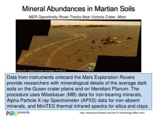
The presentation provides a comprehensive overview of the MEP project focused on designing a deployable greenhouse for a robotic Mars lander. It details project objectives, design elements, and systems utilized, including mechanical and electrical designs. Key requirements include an inflatable structure with specific dimensions and weight limits, thermal systems for temperature control, and an integration and test plan. The review addresses descoping elements and emphasizes key actions required to meet mission objectives, ensuring the greenhouse's functionality on Mars.

E N D
MEP(Martian Environmental Pod) Critical Design Review Fall 2003 Aerospace Engineering Department University of Colorado-Boulder
Presentation Overview • Descoping the Project • Request for Action (RFA’s) • System Architecture • Mechanical Design Elements • Electrical Design Elements • Integration Plan • Verification and Test Plan • Project Management Plan
Descoping the Project • Thermal System • 1 DOF instead of 2 DOF • “Flower configuration” not necessary due to no requirement of light concentration • No phase change materials (paraffin) due to complexity • Actuation System • Paraffin actuator to mechanical system
Project Objective The overall objective of the proposed project is to conceive, design, fabricate, integrate, test and verify a deployable greenhouse for a robotic Mars Lander.
Project Requirements • Inflatable and deployable structure • Capable of housing one Arabidopsis plant but dimensionally not exceed 25’’ x 25” x10’’ • Mass must not exceed 3.5 kg (7.72 lbs) • Power consumption must not exceed: • 16 W-hrs. at night • 30 W-hrs during the day • Maintain delta pressure at 10 – 50 kPa • Monitor temperature inside greenhouse and reduce heat loss
System Architecture • Greenhouse • Greenhouse structure • Mounting hardware • Pressure system • Thermal Shield and Structure • Platform • Petals with gear and axle • Electrical System • Power supply • Software • Sensors • Thermal Actuation
Stored System • Dimensions: 21.75’’ x 8.3’’ x 4.3’’ • Under initial condtions • Configuration for flight • Greenhouse structure is deflated • Configuration for daytime • Greenhouse structure is inflated • Allows for photosynthetic light
System Design • Configuration for night • Retards heat loss • Protects greenhouse from dust storms
Greenhouse Design Elements James Ball
Manufacturing Enclosure Material: • Kapton HN (Type 100) Manufacturing: • Shell made out of rectangular piece of Kapton and fastened with solvent. • Circular top will be attached to one end with solvent
Stress on Greenhouse • Stress • Tensile Stress of Kapton = 165 MPa
Mounting Greenhouse • Cylinder will be sealed around ring using solvent • The ring will be secured to the top box using screws and a rubber o-ring
Pressure System • Single gauge regulator - Output: 0 - 6080 kPa - 60 psi safety relief valve - Feed the control valve gas at 50 kPa • 5 lb CO2 Tank
Control Valve • Latching-type, high density, interface 3-way solenoid valve - 5 Volts - 1100 Lohm ( 1.5 minutes to inflate) - 5.5 mW per switch - Dimensions: 1.12" long x 0.28" in. diameter - Mount in electronics package with tubes running into greenhouse
Control Valve Mounting • Mounted on the platform next to the gear slot • Will be underneath the top box • A small tube through top of box to enclosure
Check Valve • CCPI55100695 check valve - Cracks at 69 kPa - Flow rate = 250 Lohm - Passive - 5.5 mm diameter and 7.5 mm length - Mounted in the top box with one end inside of the enclosure
Check valve Mounting Will mount at the top of box with one end in the greenhouse Solvent to hold it in place
Pressure System Tank Regulator Control Valve Greenhouse Check Valve
Test Plans • Verify that the valve inflates enclosure to 50 kPa and then turns off • Fulfill the requirement that the enclosure is inflatable • Interpret the data to analyze how well it maintains proper pressure levels • Basic set up will include a CO2 tank, and a regulator to send CO2 to the control valve • This test will also be done in a wind tunnel and outside in the cold to verify that it operates in various conditions
Thermal Shield and Assembly Sara Stemler
Material Aluminum • densityal = 2700 kg/m3 • k = 237 W/m*K Acrylic • densityacrylic = 1400 kg/m3 • k = 0.27 W/m*K Acrylic reduces the weight and has a lower thermal conductivity by a magnitude of 10
Thermal Analysis Thermal Conductivity • kKapton = 0.12 W/m*K • kacrylic = 0.2 W/m*K Thickness of Material • tKapton = 5 mil • tacrylic = 0.1’’ Heat Transfer Rate
Torsion Analysis Shear stress: Polar Moment of Inertia: Torque: T = F*d
Torque Analysis • Torque produced by petals = 367 oz-in. • Diameter of rod > 0.083 in. • Shear modulus (G) of acrylic = 167,000 psi • Polar moment of inertias (r = 0.25 in.) • Solid rod = 3.8*10-4 m4 • Hollow rod = 3.6*10-4 m4 JH > Js meaning lower stresses and less weight
Gearing System • 4:1 gear ratio will quarter the torque necessary to operate the petals • 0.5’’ diameter gear mounted on motor shaft • 2’’ diameter gear mounted on axle
Petal Assembly • Varies in length from 7.5’’ – 14.25’’ • Varies in width from 6.5’’ – 8.3’’ • Tabs are placed along each petal to “catch” the subsequent petal during deployment
Electrical Design Elements Tod Sullivan
Electronics Overview • Objectives • Measure pressure and temperature • Control pressure with Lee Co. Micro-Valve • Open/close thermal shield • Plot pressure vs. time & temperature vs. time
Valve Plot Temp vs. Time Temp NC Limit Switch Read Voltage Input Calculate Temp Store to file Solar Panel + 5 V daylight 0 V night + If P >= 50 kPa, then output 0 V If P < 50 kPa, then output 5 V 5V Power Supply Relay Motor Read Voltage Input Calculate Pressure Store to file + Plot Pressure vs. Time NC Limit Switch Pressure
Electronic Subsystems • Power Supply • Software • Sensors • Thermal Actuation
Electronic Subsystems • Power Supply • 5 V fixed • 3 A max current • Tektronix PS280
Electronic Subsystems Plot Temp vs. Time • Software • LabView Tacklebox Station • LabView • BNC Terminal Block • DIO Channel • Analog Input (Pressure Sensor) • Analog Input (Temperature Sensor) • 12 bit DAQ Card Read Voltage Input Calculate Temp Store to file ACH 1 If P >= 50 kPa, then output 0 V If P < 50 kPa, then output 5 V DIO 1 Read Voltage Input Calculate Pressure Store to file ACH 0 Plot Pressure vs. Time
Electronic Subsystems • Thermistor • Omega 44000 series • 2252 Ω • R1 = 1000 Ω • Resolution: 0.1 °C 5V R1 V
Electronic Subsystems • Pressure Sensor • Omega PX139 Differential Pressure • 4 V span of 30 psi • Vres = 0.9 mV • Resolution: 0.5 kPa 5V V
Electronic Subsystems • Thermal Actuation • DC motor open/close the thermal shield • 5 V power supply • Theoretical torque of 367 oz-in • Faulhaber 2342-006CR • Torque rating = 12.35 oz-in • 5 rpm • 0.1944 lb • Faulhaber 23/1 planetary gearbox • 989:1 ratio • 0.2425 lb
DC Motor NC Limit Switch Solar Panel + 5 V daylight 0 V night + 5V Power Supply Relay Motor + NC Limit Switch
DC Motor • Limit Switch • 3 A rated limit switch • NC • Relay • Potter & Brumfield • R10E1Y2S200 DPDT • 2 A • 5 V coil • Solar Panel • 5 V • 100 mA • SC-1 Solar World
Power Analysis • Power consumption • Valve • 5.5 mW-s • Initial fill time = 1.02 min. • Pressure Sensor • 5V * 2 mA = 0.01 W • Thermistor • 5V * 1.5 mA = 0.0077 W • DC motor • 5V * 1 A = 5
Power Analysis Power Limit Initial Gas Fill Motor On
Power Analysis Total Power Valve Power Sensor Power
Power Analysis Power Limit Day Power Limit Night Motor Operation
Electronic Noise Analysis • Noise • Usual noise from lab stations • 0.02 mV • Signal Resolution • 0.01 v • Signal to Noise Ratio • Noise at 0.02 mV • S/N = 50 • Noise at 1 mV • S/N = 10
Electronic System • Mass & Cost Distribution