EVLA Overall System Specifications
EVLA Overall System Specifications. Rick Perley EVLA Project Scientist. EVLA Design Philosophy. The EVLA Project has never intended to build an entirely new telescope. The design approach has always been to maximize the increase in observational capabilities by combining:

EVLA Overall System Specifications
E N D
Presentation Transcript
EVLA Overall System Specifications Rick Perley EVLA Project Scientist
EVLA Design Philosophy • The EVLA Project has never intended to build an entirely new telescope. • The design approach has always been to maximize the increase in observational capabilities by combining: • Existing infrastructure (array, antennas, people …) • Modern technologies • It was clear early in the design process that an order-of-magnitude improvement in all key observational capabilities was both feasible and practical. EVLA Advisory Panel Meeting 10/11 June 2002
EVLA Science Goals • An order-of-magnitude improvement at modest cost sounds good, but the expenditure must be justified by the potential science return. • Important design philosophy – the EVLA, like the VLA, is to be a general-purpose, flexible instrument, for astronomical research. • A series of meetings resulted in a wide-ranging comprehensive science case, which was included in the proposal to the NSF for Phase I funding. EVLA Advisory Panel Meeting 10/11 June 2002
Top-Level EVLA Technical Goals An early review of potential capabilities resulted in the following top-level technical goals: • Complete Frequency Access (300 MHz – 50 GHz) with the best ‘G/T’ at each band. • Up to 8 GHz (per polarization) instantaneous BW • A wide BW, extremely highly linear, full-polarization correlator with at least 16,000 channels, up to 1 Hz resolution, pulsar binning, subarraying, and VLBI-ready capabilities. EVLA Advisory Panel Meeting 10/11 June 2002
Top-Level EVLA Technical Goals • Improved low-surface brightness imaging capability • A factor of ten increase in resolution, with excellent imaging capability. • Be able to incorporate VLBA antennas in the future. • Improved operations and user interaction capability. EVLA Advisory Panel Meeting 10/11 June 2002
The Two Phases • An early decision: -- split the project into two phases. • Phase I: Essentially an upgrade to the VLA. • Funding secured (mostly – final word on correlator funding expected shortly) • Two components of the original Phase I plan were deferred to Phase II, primarily for budgetary reasons. • Phase II (Completion Phase): Primarily an expansion. • Not yet funded – a proposal is under development. • Will be discussed tomorrow EVLA Advisory Panel Meeting 10/11 June 2002
EVLA Technical Goals • The top-level EVLA goals were presented to meetings of our scientific users, with the questions: What potential science can you foresee? What further capabilities are needed to get the best science from this instrument? • The responses (in the form of typical and extreme observational programs) enabled a more detailed set of technical goals for the project. • The more detailed ‘Level 2’ technical goals are: EVLA Advisory Panel Meeting 10/11 June 2002
Antenna -- Mechanical • Pointing: • Blind: 6” rss between 30 and 70 degrees El. • Referenced: 3” rss between 20 and 70 deg. El. • OTF: 4” rss at drive rates up to 1 deg/min • 8”, rss, at rates from 1 to 2.5 deg/min. • Subreflector Positioning • Limits on focus, horizontal, rotation, and tilt positioning, and band change speed which are each about a factor ~2 tighter than current. • Note: These goals are close to values already achieved – there is no specific EVLA budget for improvement. EVLA Advisory Panel Meeting 10/11 June 2002
Antenna -- Mechanical • Antenna Slew/Settle • < 5 seconds, when angular motion is less than 30 arcminutes. Driver for the above: Mosaicing and OTF imaging at high frequencies. • Cassegrain Feed Positioning • 5 arcminutes. Driver: Hi-Fidelity, full-beam imaging (feed illumination offsets place phase gradient across primary beam). EVLA Advisory Panel Meeting 10/11 June 2002
Antenna - Electrical • Efficiency Driver: EVLA Sensitivity Goal of < 1 mJy in 12 hours. EVLA Advisory Panel Meeting 10/11 June 2002
Antenna -- Electrical • Main-Beam Similarity • Power variation < 3% of peak, within FWHP. • Phase variation < 0.2 deg (L-band) to 5 deg (X-band and higher) with FWHP. • Illumination Centroid • Centroid within 10 cm of the antenna center. Driver: Minimization of computing efforts for full-field and mosaic imaging. EVLA Advisory Panel Meeting 10/11 June 2002
Antenna - Electrical • Polarization • Stability (stable weather, within FWHP, 8 hr) • RCP and LCP polarization ellipses stable to 0.002 in axial ratio, and 2 degrees in position angle. • Ellipticity and Orthogonality • RCP and LCP on-axis AR to be 0.9 to 1.0 • RCP and LCP major axes orthogonal to 10 degrees. • ‘Squint’ Stability • Separation of R and L beams to remain constant to 6 arcsec. • Driver: High-fidelity polarimetric imaging. EVLA Advisory Panel Meeting 10/11 June 2002
Antenna - Electrical • Receivers • Tsys • Ae/Tsys EVLA Advisory Panel Meeting 10/11 June 2002
Antenna-Electrical • Performance Variation over Frequency: • Increase of Tsys within any band, relative to best value, to be less than • 3dB over full bandwidth • 1 dB within inner 85% of BW • Driver: To ensure sensitivity goal over wide bandwidth. EVLA Advisory Panel Meeting 10/11 June 2002
Antenna - Electrical • Receivers • Power Linearity • Better than 0.5% over input power range of 15 dB. Driver: Accurate (relative) flux density calibration • Better than 2% over input power range of 50 dB. Driver: Solar observing, and tolerance to RFI. • Time Response • 0.5% power linearity condition to be maintained on 20 ms timescale. Driver: OTF imaging and solar flare observations EVLA Advisory Panel Meeting 10/11 June 2002
Antenna-Electrical • Temporal Phase Stability • 1-s variations < 0.5 ps on timescales < 1 sec. • Slope < 0.2 ps/min over durations < 30 min. • Variations about this slope < 1.4 ps. • Angle-dependent phase changes less than: • 0.7 ps for any angle change • 0.07 ps for antenna angle changes < 10 degrees. Driver: Phase-coherent capability at 50 GHz. EVLA Advisory Panel Meeting 10/11 June 2002
Antenna - Electrical • Receivers – Bandpass Characteristics • Amplitude Stability • Variations (power) < 0.01% on timescales < 1hr, over frequency scales < n0/1000. • Phase Stability • Phase variations < 5 millideg, on timescale < 1 hr, over frequency scales < n0/1000. Driver: Sensitive absorption line studies (high spectral dynamic range). EVLA Advisory Panel Meeting 10/11 June 2002
Antenna - Electrical • Receivers – Bandpass Characteristics • Gain Slope • Power gain variations < 3dB across full bandwidth • Gain variations – limits on gain slope which vary with band. • Gain Ripples • < 0.25 dB on band-dependent frequency scales • Phase Ripples • < 2 electrical degrees, on band-dependent frequency scales. Driver: To limit closure errors to reach dynamic range goal of 70 dB. EVLA Advisory Panel Meeting 10/11 June 2002
Antenna - Electrical • Receivers – Tolerance to Power Spikes • Ability to absorb 10 mW for 1 second without permanent physical damage. • Driver: To handle RADARSAT-like emission seen through the main beam. EVLA Advisory Panel Meeting 10/11 June 2002
Time Accuracy • Time • System time accurate to 10 nsec. Driver: Pulsar timing observations. EVLA Advisory Panel Meeting 10/11 June 2002
Correlator • Bandwidth • Variable, up to 8 GHz per polarization • Polarization • Full polarization capabilities. • Frequency Resolution • Variable, from ~ 1 MHz to 1 Hz. • Number of Channels • At least 16,384 • Time Resolution (dump speed) • Better than 10 msec EVLA Advisory Panel Meeting 10/11 June 2002
Correlator • Pulsar modes • Binning capability, with > 1000 bins, each with full spectral capability and 200 msec time resn. • Subarray capability • At least 5 simultaneous subarrays. • Phased Array capability • Required, for each subarray. • Linearity (spectral dynamic range) • > 50 dB (H2O masers, tolerance to RFI) EVLA Advisory Panel Meeting 10/11 June 2002
Correlator • Baseline Range • To continental scales • VLBI capabilities • VLBI-ready (tape or real-time) • RFI tolerance • > 50 dB spectral linearity • Ability to avoid strong RFI Driver: To enable the EVLA to achieve its science goals! EVLA Advisory Panel Meeting 10/11 June 2002
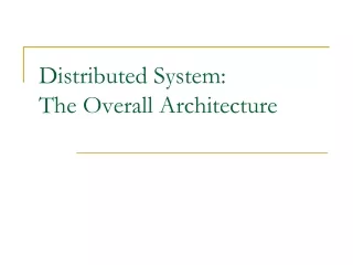
Proposal Preparation and Submission Observation Preparation Observation Scheduling Data Archive Image Pipeline Data Post-Processing Monitor and Control System Correlator Antenna Feed Receiver IF System Fiber Optics Transmission System Local Oscillator NRAO Data Management Group (e2e project) EVLA Project Canadian Partner Primary data flow Figure 3.1. Principal EVLA Subsystems Control and monitor flow
Operational (M&C) • The specific requirements for the M&C System are given in EVLA Memo #15 (Benson and Owen). • Key Top-Level Goals: • Replace the ModComps, and control current VLA hardware. Continue to use existing control scripts (OBSERVE/JOBSERVE) • Control a hybrid VLA/EVLA, during the transition phase. • Control the EVLA, the NMA, and fiber-linked VLA Antennas EVLA Advisory Panel Meeting 10/11 June 2002
Operational (M&C) • Specific Scientific Goals for the M&C System include the following • Spectral Line Imaging • Mosaicing • Observations of solar system objects • Solar observing • Astrometry • Rapid response to transient sources • VLBI/VLBA observing EVLA Advisory Panel Meeting 10/11 June 2002
Operational (M&C) • Specific Scientific Goals for the M&C System include the following (cont.): • Pulsar observing • Total Power measurements • NMA/PT Link/future real-time VLBA • Miscellaneous (currently unplanned) items. EVLA Advisory Panel Meeting 10/11 June 2002
Operational (M&C) • Scientific Goals include: • Recommended minimum output data rate • Hardware reconfiguration times • Subarrays • Interferometer model • Management of correlator modes and times • Special observing modes – phased array, reference pointing, focus, tipping scans, holography, survey modes • Support for special hardware: GPS, API, WVR, etc. • RFI detection, avoidance, excision • Archive of monitor data and observation parameters EVLA Advisory Panel Meeting 10/11 June 2002
Astronomer-Instrument Interfaces • Part of the e2e project. • Proposal Submission and Handling • Observation Preparation and Scheduling • Observation Control and Feedback • Data Archive • Pipeline Processing – default images • Data Reduction Software EVLA Advisory Panel Meeting 10/11 June 2002