USB Controlled IO Module
USB Controlled IO Module. A 499a Project. Jon Knoll Dave Wolowicz Sponsored by: Dr. Kin Li. Objective. To create a low cost automation control using the USB Protocol. This I/O module is to be a replacement for the Festo EasyPort D16.

USB Controlled IO Module
E N D
Presentation Transcript
USB Controlled IO Module A 499a Project Jon Knoll Dave Wolowicz Sponsored by: Dr. Kin Li
Objective To create a low cost automation control using the USB Protocol. This I/O module is to be a replacement for the Festo EasyPort D16. The following design requirements were created at the beginning of the project: • 16 Digital Inputs & 16 Digital Outputs (24V) • Pin compatible with Festo EasyPort D16 • Must fit in the same enclosure as the Festo EasyPort D16 • Input/Output Indicator Lights • Plug and Play USB Interface • Optical isolation between USB and I/O Ports • 5A loading capability per output • Low Cost Pricing
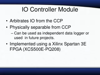
Steps: 1. Decide on the main architecture based on the design requirements 2. Design each subsystem, and calculated the requirements for each component. 3. Select components, ensure each component meets our specifications (and also ensure that we are using the component within its specification). 4. Build and test prototypes of each subsystem to verify the design. Modify the design where necessary. 5.Draw the schematic diagram. Our Design: Our board is designed from scratch. It is designed to be simple and cheap yet reliable. Our circuit uses a PIC 16C745 for USB communications. It also writes to the outputs and reads the inputs. Each output uses a high current MOSFET All inputs/outputs are optically isolated from the computer. Circuit Design
The USB Protocol A USB device carries all of its critical information with it such as: • Type of device • Country of origin • Developing company • Product identification • Size and type of communications • Required power consumption The flowchart shows how the USB protocol registers a device and sets up the communications for it. (enumeration)
Software To communicate with the device we used an Human Interface Device (HID) driver. The main reasons for using an HID driver are: • Comes standard with Windows • Did not need to write a kernel level driver from scratch • Supports nesting and collections • Ease of programming I/O Module The flowchart shows how data is transferred from the application through the drivers and to the device
Make the Printed Circuit Board Steps: 1. Make the component “footprints” (images of the components on the PCB, to show where the pins go). 2. Measure critical placement components, the components that need exact placement (like the LEDs and the connectors). 3. Lay out the rest of the components by functionality and asthetics. 4. Manually route the important traces (traces - strips of copper that connect two points electrically) 5. Autoroute the rest of the traces. 6. Double check everything, particularly hole sizes, and perform an electrical rule check. 7. Email the files to a PCB manufacturer 8. Populate the board (ie. put the components on it
Marketing The device is built to be a low cost solution. Applications for the module include: • Low cost basic PLC replacement • Computer interface for laboratories • Process simulator • Home automation control box • I/O for home hobbyists