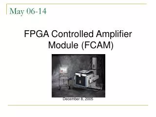
FPGA Controlled Amplifier Module Development for Spectrum Analysis
430 likes | 552 Vues
This project involves the design and testing of an FPGA-controlled amplifier to serve as a pre-amplifier for a PC-based spectrum analyzer developed by a previous team for Teradyne Corporation. Our team focused on understanding the existing design, assembling the board, and creating a detailed test plan. Key tasks included research, verification of the previous design, implementing corrective measures for any assembly errors, and developing automated testing protocols using LabVIEW. The end product will include an assembled board, updated design, completed test plans, and thorough documentation.

FPGA Controlled Amplifier Module Development for Spectrum Analysis
E N D
Presentation Transcript
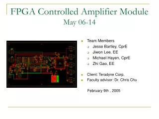
FPGA Controlled Amplifier ModuleMay 06-14 • Team Members • Jesse Bartley, CprE • Jiwon Lee, EE • Michael Hayen, CprE • Zhi Gao, EE • Client: Teradyne Corp. • Faculty advisor: Dr. Chris Chu April 25th , 2006
Presentation Outline • Introductory Materials • Project Activity Description • Design Overview • Implementation • Testing • Resources and Schedules • Closing Materials May 06-14
List of Terms and Definitions • Bill of Materials – List of Components and their cost • DAC – Conversion of a digital signal to an analog sampled signal • DC-offset– given signal source does not have the correct 0-crossing but shifted down or up. • FPGA – Field programmable gate arrays, allows us to control some the circuits automatically • Gain – The ratio of the output amplitude to the input amplitude • HDL – Hardware Description Language • Noise – Undesired interference in signals • Spectrum Analyzer – A computer-based tool that analyzes signals in the frequency domain • THD – Total harmonic distortion, the ratio between the powers of all harmonic frequencies above the fundamental frequency May 06-14
Acknowledgement • Teradyne Corporation • Jacob Mertz • Ramon De La Cruz • Steven Miller • Additional Help • Jason Boyd • Dr. Robert Weber May 06-14
Problem Statement & Approach • Problem statement: • To build and test the FPGA controlled Amplifier for PC based Spectrum Analyzer developed by previous team • Approach: • Understand existing design • Board assembly and bring-up • Make detailed test plan • Perform and document tests May 06-14
Users, Uses & Operating Environment • Primary users • Engineers at the Teradyne Corporation • Product function • As a pre-amplifier for the signal input to a PC based spectrum analyzer device. • PC based spectrum analyzer was designed by previous phase • Climate-controlled laboratory (low humidity) • ESD (Electro Static Discharge) May 06-14
Assumptions and Limitations • Assumptions • The end product will not be sold to other companies. • The design provided by the previous team is valid. • Necessary equipment will be available. • Limitations • Equipment must be available on campus • The design must meet specifications May 06-14
Previous Accomplishments • General Design • Untested FPGA code • Design Schematic • Bill of Materials • Partial assembly of board May 06-14
Present Accomplishments • Ordered parts and assembled board • Researched and verified design • Re-vamped FPGA code • Made detailed test plans • Developed automated tests • Identified and resolved board errors May 06-14
End Product & Other Deliverables • An assembled board • Updated design • Completed test plans • Automated LabVIEW tests • Documentation of all activities May 06-14
Approaches Considered and one used • Approaches considered: • Manual testing and calculation • LabVIEW automated testing and Excel calculation • Choice: LabVIEW automated testing • Repeatability • Self documentation • Speed/efficiency • Extra research required May 06-14
Project Definition Activities • Goals of this project: • Research & verify the previous design • Meet the specifications • Board Assembly • Make a detailed test plan • Testing • Document all processes May 06-14
Research Activities • Study previous team’s design • Pspice simulation • Test methodologies • Noise • THD • LabVIEW May 06-14
Design Activities • Verification of design • DC Offset Correction • Operational Amplifier • Tests design • DC Offset Correction verification tests • Amplifier performance tests May 06-14
Circuit Overview May 06-14
Implementation Activities • Errors on the PCB were fixed • New Pspice Simulation was developed • Trouble shoot for unexpected oscillation • Specifications were adjusted • Test strategy was developed according to Client suggestions May 06-14
PCB Board Adjustments • New parts purchased and soldered • Pins of voltage regulators switched • Pins of op-amps switched • Fixed incorrect supply voltage • FPGA code fixed May 06-14
Unexpected Oscillation • Frequency: 32 – 60MHz • Amplitude: 5-10Vpp • Potential causes • External Noise • Error in assembly • Parasitic capacitances • Unstable amplifier design May 06-14
Unexpected Oscillation May 06-14
Cause of Oscillations • External Noise • Twisted wires at inputs • Tested in alternate location/alternate equipment • Error in assembly • Corrected error with voltage regulators in layout • All essential parts replaced • Parasitic capacitances • PSPICE models also showed oscillations (without capacitors) • Other debugging • DC offset correction adjusted • Comparator circuit disconnected • Both current feedback and voltage feedback amps • Conclusion - Unstable amplifier design May 06-14
Pspice Simulation • Developed in Orcad Student 9.1 • Purposes • Help determine new specifications • Help find new resistor values • Help troubleshooting May 06-14
PSPICE Model May 06-14
PSPICE Simulation • New resistors: • Maximize the bandwidth • Achieve best response flatness May 06-14
DC — 1kHz Input +/- 5 volts 6, 20, 40, 60 +/- 10 volts 0.5 dB < - 105 dB Total 1.5 nV/rtHz Input Voltage Available Max Output Freq Response Harmonic > 1kHz - 20 kHz +/- 5 volts 6, 20, 40, 60 +/- 10 volts 0.5 dB < - 95 dB 1.5 nV/rtHz Frequency Range Gain Settings Voltage Flatness Distortion Noise > 20kHz - 100kHz +/- 2.5 volts 6, 20, 40 +/- 5 volts 0.50 dB < -85 dB 2.5 nV/rtHz Range (Volts) (dB) (Volts) (dB) (dB) (nV/rtHz) > 100kHz - 1MHz +/- 2.5 volts 6, 20, 40 +/- 5 volts 0.50 dB < - 80 dB 3.5 nV/rtHz > 1MHz - 10MHz +/- 2.5 volts 6, 20, 40 +/- 5 volts 0.50 dB < - 70 dB 3.5 nV/rtHz > 10MHz - 20MHz +/- 2.5 volts 6, 20 +/- 5 volts 0.50 dB < -65 dB 3.5 nV/rtHz > 20MHz - 50MHz +/- 1.0 volts 6, 20 +/- 2.0 volts 1.00 dB < -50 dB 5.0 nV/rtHz > 50MHz - 100MHz +/- 1.0 volts 6, 20 +/- 2.0 volts 2.10 dB < -40 dB 5.0 nV/rtHz Changed Specification May 06-14
Testing • Goal: verify compliance with specifications • Important considerations • Documentation • Usability • Repeatability • Automated Testing • LabVIEW • Data stored in Excel May 06-14
Testing (Cont.) } • Tests • DC gain test • Gain flatness and bandwidth test • Total harmonic distortion test • Circuit noise test • VHDL code behavior test • DAC control test • Offset calibration test • Offset correction verification test Amplifier Tests } DC Offset Tests May 06-14
Amplifier Tests • DC Gain Test • Pure measure of DC gain • No AC effects • Gain Flatness and Bandwidth Test • AC input across 0-100MHz range • Verify flatness is within specification • Ensures consistent gain • Total Harmonic Distortion • THD = Distortion at multiples of input frequency • Performed with spectrum analyzer • Noise Test • Ambient noise created by op-amps • Also measured by spectrum analyzer May 06-14
DC Offset Tests • VHDL Behavior Test • Tests just behavior of algorithm • Simulated on PC in ModelSim • DAC Control Test • Custom FPGA code • Ensures DAC produces correct offsets • Performed in circuit • Offset Calibration • Artificially inject range of offsets • Calibrate for each, verify correction • Offset Correction Verification Test • Ensure calibration holds when AC signal is applied • Final assurance individual systems work well together May 06-14
Personnel Effort Requirements Task 1 – Problem definition Task 2 – Research previous phases to understand the designs project Task 3 – Identify errors and documentation Task 4 – Test plan design Task 5 – Assemble board and bring up Task 6 – LabVIEW development and Testing Task 7 – Final report and presentation May 06-14
Financial Requirement May 06-14
Project Evaluation May 06-14
Project Schedules May 06-14
Project Archive Folder May 06-14
Additional Work • Recommended work • Correct design to eliminate oscillations • Re-build prototype board accordingly • Verify specifications with LabVIEW tests • FPGA control of gain • Frequency response calibration • Future integration with Spectrum Analyzer • Once above recommendations are met May 06-14
Commercialization • Recommended additional work required • Packaged with PC based spectrum analyzer • Price to be determined • Potential Market • Small technology companies May 06-14
Lessons Learned • Experience gained • Documentation methods • Team Work • Working with an outside client • Following schedules • Test procedures • Test implementation • LabVIEW development May 06-14
Risk and Management • Unexpected test results • Conduct proper trouble shooting • Loss of a team member (Did not encounter) • Work cooperatively • Good communication • Keep updating all processes on the website • Hardware Damage • Quick replacement and backup board • Design Problem • Identify the problem and suggest for the next phase • Specifications not practical • Define new specifications (with client input) May 06-14
Closing Summary • Team’s Accomplishments • Assembled the prototype • Developed FPGA code • Developed Test plans and LabVIEW programs • Documented and organized work • Debugged the product and identified problems • Project will make contribution • Teradyne • PC-Based Spectrum Analyzer Product • The team received the following benefits: • Technical knowledge • Team work • Real industry project • Overall, project benefits both the client and the team May 06-14
Questions? May 06-14