Download
1 / 19
190 likes | 202 Vues
This study aims to investigate dosimetry techniques for low energy protons using ionization chambers, radiochromic films, and silicon detectors. The results will contribute to improving proton beam therapy.

E N D
A study of dosimetry for low energy protons with ionization chambers, radiochromic films and silicon detector. Cristina Battaglia Supervisors: Prof. M. I. Gallardo, Dr. D. Schardt, Prof. J. Espino 3rd ELIMED workshop, Catania, 7th-9th September 2016
Introduction (1) Introduction Whyprotonbeamsfortherapy?? • Benefitsoverconventionalradiotherapy (electronsorphotons). • Proton dose profile characterized by a sharp maximum at the end of the range in tissue, Bragg peak (BP). • Advent of new commercialequipmentswithaffordablecosts. 3MV Tandem accelerator (CNA, Seville) provides proton beams of maximum energy of 6 MeV. Useful for radiobiology and dosimetry studies at the interesting region of the Bragg peak. 3rd ELIMED workshop, Catania, 7th-9th September 2016
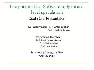
Introduction (2) Introduction Energy 150 MeV Relative ionization (a.u.) Depth in water (mm) Provided by D. Schardt 3rd ELIMED workshop, Catania, 7th-9th September 2016
Experimental setup: beamline • Au target (thickness 5.4 mg/cm2) to scatter and obtain a homogenousbeamprofileontothesamples. • Fast-closingvalve (100 ms) used as a beam-shutter. 5155 mm Au target Manipulator Sample irradiation setup 3rd ELIMED workshop, Catania, 7th-9th September 2016
Experimental setup: sample irradiation At the exit of the tracking chamber: • Thin vacuum exit window (kapton, thickness 50 µm, diameter 44 mm, ΔP≈10-6 mbar). Kapton window IC • Ionization chamber (IC) (three parallel electrodes 7.5 µm thick, two air gaps 6.5 mm,operated at VIC=400 V) to measure the proton fluence and monitor the dose, connected to a Keithley electrometer (model 6514). • Holder with six positions designed for biological samples and also used for films. Holder + film Electrometer Setup for sample irradiation: beam energy can be degraded with mylar foils between the IC and the film 3rd ELIMED workshop, Catania, 7th-9th September 2016
Experimental setup: sample irradiation (2) At the exit of the tracking chamber: Kapton window + collimator • Vacuum exit window, diameter reduced to 20 mm. ICs Electrometer • A tableequippedwith a micrometric linear driver (Mitutoyo) withadjustableheight. • Holder mounted on the driver adapted to host: IC, radiochromic films and silicon detectors. Precision linear driver Setup to change passively the beam energy using air as a degradator 3rd ELIMED workshop, Catania, 7th-9th September 2016
EBT3 Gafchromic films as dosimeter Characteristics: Analysisdevice & software Polystyrene 125µm Active layer 28 µm Epson perfection V700 photo scanner Polystyrene 125µm • Transmission mode • 48-bit RGB (Red Green Blue) mode. • No colour correction activated. • Tiff image acquired. • 75 dpi (dots per inch resolution). Irradiated film with six amounts of dose. Transversal view: EBT3 technology For photons and electrons: • Underionizingradiation, thesensitive gel layerpolimerizes, and the film turns blue. • Symmetricconstruction. • Energyindependence. • High spatialresolution (25µm). • Tissueequivalence. • No chemical, thermaloropticaldevelopment. Not always for protons! Image J: software of public domain for Java image processing • Usedfor EBT3 analysis in terms of: • beamprofilechecking; • absorbed dosecalibration of theradiochromic films. 3rd ELIMED workshop, Catania, 7th-9th September 2016
Dose calibration Standard protocol*: Photons • Photonsdeliveredby a 6MV Siemens clinicallinac (at Virgen Macarena Hospital). • Source to Surface Distance of 100 cm + 1.5 cm of solidwaterabovethe film. 100MU correspond to 100cGy Protons Upstream the Bragg peak region, the dose calibration with photons is valid also for protons (similar Linear energy transfer, LET, outside the Bragg peak) [1]. [1] M. C. Battaglia et al., Phys. Rev. AB, 19, 064701 (2016) 3rd ELIMED workshop, Catania, 7th-9th September 2016 *R. Arráns, et al., Rev. Fis. Med, 2009; 10(2):83-104.
Results: DIC vs DEBT3 Dose results: film vs Ionization Chamber Dfilm (Gy) DIC (Gy) (2) where dE/dx is the stopping power (calculated considering an initial energy of 5.233 MeV) and ρ (1.2 g/cm3) is the density of the active layer. 3rd ELIMED workshop, Catania, 7th-9th September 2016
Moving to the Bragg peak Energy beam degradation (2) Two methods to passively degrade the beam energy Mylar foils EBT3 film polyester polyester active layer active layer Air gaps polyester polyester IC IC EBT3 film Monte Carlo simulation (SRIM2008) 3rd ELIMED workshop, Catania, 7th-9th September 2016
Silicon detector measurements Dose results: film vs Ionization Chamber Experimental setup Energy measured at the same position of the EBT3 films, interposing several mylar foils Ion implanted silicon detector ORTEC preamplifier Results 3rd ELIMED workshop, Catania, 7th-9th September 2016
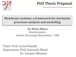
Saturation effect Bragg peak approaching the active layer: DEBT3/ DIC= 0.69 ±0.06 - 0.82± 0.07 DIC DEBT3 • Quenching effect noticed betweeen 19 and 51 µm of mylar. • Marked effect when the maximum lies in the active zone for • 32 - 45 µm of mylar. In high-dose gradient region, the film becomes sensitive to LET. Maximum in the active layer: DEBT3/ DIC = 0.69 ±0.06 – 0.71± 0.07 3rd ELIMED workshop, Catania, 7th-9th September 2016
Geant 4 simulation G4 version 10.1.2 (EmStandard_opt3), example TestEm11: computing the depth dose profile • Absorbers: • IC: threekaptonelectrodes (G4_KAPTON, 7.5 µm thick, ρ= 1.42 g/cm3) and two air gaps (G4_AIR, 6.75 mm thick, ρ= 0.0012 g/cm3) • EBT3: NIST compounds, twopolystyrenelayers (G4_POLYSTYRENE, 125 µm thick, ρ= 1.06 g/cm3) and the active zone (G4_LUCITE, 28 µm thick, ρ= 1.2 g/cm3) • Beamcharacteristics: • Energy 3.83 MeV, straggling 0.05 MeV. • Cylinder of 2cm of diamater. • Particlesshot at theleftface of thegeometry. 3rd ELIMED workshop, Catania, 7th-9th September 2016
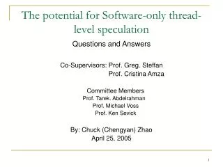
Direct measurement of the Bragg peak position Two ICs: direct measurement of the Bragg peak in ar. Geant4 maximum position 180 mm Experimental conditions: Integrated charge 100 nC, Beam energy 3.83 MeV after the first IC (used for normalization), range 20.2 cm. Measurements compared with Geant4 simulation. Range agreement: 5%. Measured maximum position 189 mm 3rd ELIMED workshop, Catania, 7th-9th September 2016
Preliminary tests Quenching like effect Dose (Gy) More experimental data are needed Air thickness (mm) 3rd ELIMED workshop, Catania, 7th-9th September 2016
Final remarks Optimization of a beamlinededicated to dosimetrystudies at the 3 MV Tandemaccelerator • Dosimetrystudieswith a new technology of radiochromic films (EBT3 GafChromic) • Dosimetryoutsidethe BP with EBT3 films isvalidatedbythe IC measurements • EBT3 films cannot be usedfordosimetryinsidethe BP, at thisstage, sincethequenchingeffectisoccurring. • Air used as degraderfurnishes a largerrange of measurements in theBraggpeakregion, allowing to have a directmeasurement of it. Next… • More experimental data are needed to establish a protocolfor film dosimetry in theBraggpeakregion. 3rd ELIMED workshop, Catania, 7th-9th September 2016
Acknowledgement Radiobiology collaboration University of Seville, Spain: GETERUS group (M. A. Cortés Giraldo, M. I. Gallardo, J. M. Quesada), J. M. Espino (also CNA). GSI, Darmstadt, Germany: D. Schardt University Hospital “Virgen Macarena”, Seville: H. Miras. University of Granada, Spain: A. M. Lallena. University Hospital “San Cecilio”, Granada, Spain: D. Guirado. 3rd ELIMED workshop, Catania, 7th-9th September 2016
Bibliography [1] M. C. Battaglia et al., Phys. Rev. AB, 19, 064701 (2016) [2] M. Muller, Diploma thesis, University of Darmstadt (2004). [3] R. Arráns et al., Rev. Fis. Med (2009); 10(2):83-104. [4] F. Fiorini et al., Physica Medica 30 (2014) 454-461. [5] S. Reinhardt et al., Radiat. Environ. Biophys. (2015) 54:71-79. [6] D. Kirby et al., Phys. Med. Biol.55(2010): 417-433. [7] S. Devic, Physica Medica (2011), 27, 122-134. [8] A. Piermattei et al., Med. Phys. 27 (7) (2000) 1655-1660. [9] J. Sorriaux et al., Physica Medica (2012), 1-10. [10] L. Zhao and I. J. Das, Phys. Med. Biol. 55 (2010), N291-N301. [11] H. Alnawaf et al., Journal of Applied Clinical Medical Physics, 13 (2012). [12] I. Daftari et al., Phys. Med. Biol. 44 (1999), 2735-2745. 3rd ELIMED workshop, Catania, 7th-9th September 2016
Any questions? e-mail: mbattaglia@us.es 3rd ELIMED workshop, Catania, 7th-9th September 2016