Download
1 / 36
360 likes | 668 Vues
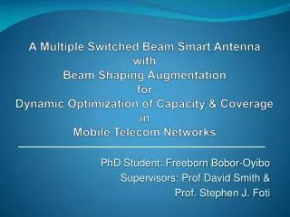
A Multiple Switched Beam Smart Antenna with Beam Shaping Augmentation for Dynamic Optimization of Capacity & Coverage in Mobile Telecom Networks . PhD Student: Freeborn Bobor-Oyibo Supervisors: Prof David Smith & Prof. Stephen J. Foti. Outline of Presentation.

E N D
A Multiple Switched Beam Smart AntennawithBeam Shaping AugmentationforDynamic Optimization of Capacity & CoverageinMobile Telecom Networks PhD Student: Freeborn Bobor-Oyibo Supervisors: Prof David Smith & Prof. Stephen J. Foti
Outline of Presentation • Background of mobile Telecommunication Networks • Overview of Smart Antennas • Standard Multiple Switched Beam Smart Antenna • Description of Proposed Multiple Switched Beam Smart Antenna with Beam Shaping Augmentation • Operation of 4x4 Butler Matrix Multi- Beamforming Network • Operation of Beam Shaping network • Overall Smart Antenna Feed network operation • Simulation of possible Dynamic Beam ‘‘states’’ • Conclusions • Future work
Background of Mobile Telecom Networks • Mobile telecom networks have evolved from 1G through to 3G • Each generation has provided increased capacity within licensed frequency bands • 1G Analogue Networks provided limited capacity mainly for Voice Telephony • 1G uses frequency division multiple access technique (FDMA) • 2G Digital Networks provide improved capacity with low data rate transmission • 2G uses FDMA, time division multiple access (TDMA) and code division multiple access (CDMA) • 3G has more capacity and a higher data rate transmission capability compared to 2G for internet and video transmission (CDMA2000,WCDMA,) • Mobile Telecoms is a fast growing business all over the world. • At the end of 2004, worldwide cellular subscription passed the 1.4 billion mark and rapid growth is expected
Current Challenges of Mobile Telecom Networks • There is need to increase coverage & capacity to accommodate more users with higher data rate demands • Conventional ways of increasing coverage & capacity: • Mast head amplifiers • Receive Diversity & Transmit Diversity • Infrastructural sharing • Higher sectorization and Adding more cells. • All of the above are useful, but limited and not dynamic.
Current Challenges of Mobile Telecom Networks cont’d • The key problem of coverage and capacity is the varying traffic load imbalance • Previous methods to accommodate varying traffic load imbalances: • Cell Spitting • Channel Borrowing • Channel Sharing • Dynamic Channel Allocation • New Soft Handover Schemes • Cell Overlay • Variable Tilt Antennas • Dynamic Cell-Size Control & Dynamic Sectorisation etc. • All the listed techniques have limitations, hence investigation into the use of smart antenna is ongoing
Unbalanced Traffic Load Sector A Sector A Sector C Sector C Sector B Sector B
Current Challenges of Mobile Telecom Networks cont’d • To accommodate the current demand of services from mobile communication user’s new intelligent or self-optimized and highly efficient systems will most certainly be required • Using the approach of a multiple switched beam antenna system and a beam shaping network, an intelligent sector optimization of varying azimuth beam shape can be established without increasing the existing electronics of the network • The proposed technique, Multiple Switched Beams Smart Antenna with Beam Shaping Augmentation can be used to dynamically optimize coverage and capacity especially for hotspots in mobile network cell sectors. • Furthermore, base stations are typically equipped with one transceiver per sector (per polarization) with a conventional sector antenna and it is cost effective not to increase the number of existing transceivers.
Current methods with Smart Antennas • Cooperative negotiation technique and semi-smart antenna[1] • Case-base reasoning with semi-smart antenna[2] • A Bubble Oscillation Algorithm for Distributed geographic load balancing in mobile networks (using smart antenna)[3] [1]. L. Du, J. Bigham and L. Cuthbert, Towards intelligent geographic load balancing for mobile cellular networks, IEEE Transactions on Systems, Man and Cybernetics, Part C, vol. 33, no. 4, pp. 480-491, November 2003. [2]. Na, Yao and L. Cuthbert,’’Resource management in 3G networks using case-based reasoning’’ International Workshop on Modeling Analysis and Simulation of Wireless and Mobile Systems, Proceedings of the 8th ACM international symposium on Modelling, analysis and simulation of wireless and mobile systems Montreal, Quebec, Canada October 2005, pp 307-312. [3]. L. Du, J. Bigham, and L. Cuthbert, "A bubble oscillation algorithm for distributed geographic load balancing in mobile networks," in The Twenty-third Annual Joint Conference of the IEEE Computer and Communications, IEEE INFOCOM'2004. Hong Kong: IEEE, March 2004.157
Overview of Smart Antenna • What is Smart antenna? • A smart antenna consists of several antenna elements whose signals are processed adaptively in order to exploit the spatial dimension of the mobile radio channel • It is not the antenna that is smart, but the antennas system • It is one of the promising technologies systems that will reduce interference and increase coverage and capacity simultaneously • The antenna system focus its radiation patterns only towards the desire user • It employs a set of radiating elements arranged in the form of an array • The signals from these elements are combined to form a switchable beam pattern that can be directed to the desire user • There are basically two types of smart antennas • Multiple Switched Beam • fully Adaptive smart antenna.
Standard Multiple Switched Beam smart Antenna MXM Beam-Forming Network Dup Switch Dup TX Dup Dup Receiver Receiver Receiver Receiver Beam Selection Combining and demodulation Figure 3.0a Switched beam system architecture
Standard multiple fixed beam smart antenna radiation pattern
Description of the Proposed Smart Antenna • The antenna has three major components, array columns, beam forming network (4x4 butler matrix) and a beam shaping network • Each array column has 17.5dBi gain • The horizontal beam shape produced by the antenna array depends on the complex weights ( magnitude and phase) applied to each array column • The beam shaping network can shape the antenna beam dynamically to the direction of maximum concentration of mobile users in a sector while still maintaining some coverage in the remaining area of the sector
XXXXXXXXXX XXXXXXXXXX XXXXXXXXXX XXXXXXXXXX Array Element Columns Dynamic Optimisation of Smart Antennasfor Mobile Telecom Networks (1) Feed Network for -45oPolarisation (Duplication of feed Network) D=Diplexer D D D D Uplink 4X4 Butler Matrix (Beamforming Network) Downlink 4X4 Butler Matrix (Beamforming Network) Proposed Design Architecture Uplink Beam Shaping Network Downlink Beam Shaping Network Feed Network for +45oPolarisation Diplexer Transceiver
Array design • Given a linear array of equally spaced identical elements, the total horizontal radiation pattern of the array E(θ) in the far field, is given by: E()= EL().AF() (1) E()dBi=EL()dBi+20log[AF()] Where: EL() is the horizontal pattern of the column element and AF() is the array factor.
Array design cont. And • d= inter-element spacing (horizontal) (72.474mm for the specific design example presented) • θ= Azimuth angle(zero at centre of sector) and n is the total number of element • is the complex weight.
Operation of 4x4 Butler matrix multi-beam forming Network • It uses combination of 90 degree hybrids and fixed transmission line phase shifters to form N simultaneous independent beams from an N element array • It performs a spatial Discrete Fourier Transform to provide overlapping orthogonal beams • Beams overlap at about 3.9dB below the beam maximum • Any signal input into one of the BM input ports will be divided equally among the output ports with a progressive phase delay • This produces the multiple beams when the Butler Matrix is connected to a linear array
BUTLER MATRIX MULTIPLE BEAMFORMER • DISADVANTAGES • Narrowband (Fixed Phase Dist.) • Only Orthogonal Beams • -13.2 dB Sidelobes • -3.9 dB Beam Crossovers • Network Cross- • overs Req’d • Network Losses • PIMs(many • connections) • Binary No. of • Beams • ADVANTAGES • Commercially Available • Low Inter-Port Coupling • Real-Time Beam Formation 3 2 4 1 0o -90o 90o Hybrids 45o 45o Beam Ports 1 3 4 2
Operation of Beam shaping Network • The beam shaping network is a variable 4-way power divider/combiner that utilizes a 2-way variable power divider/combiner to drive two 2-way power divider/combiner • When two 3dB hybrids are arranged as shown in the figure above, the output signals are given by the equation • For equal amplitude & phase ΔΦ = 270 degree. • Table 1.0 below shows the operation of the 2-way power divider
To/From Butler Matrix Beam Ports 1,2 ,3 & 4 -135o -135o Q Q Q Q Q Q Input Signal Dynamic Optimisation of Smart Antennasfor Mobile Telecom Networks (2) a3 a4 a5 a6 -2 -3 a1 a2 Beam Shaping Network -1
Operation of Beam shaping Network cont Table for the Three 2-way power divider/combiner states
Simulation of possible Dynamic Beam ‘‘States’’ • To verify the performance of the proposed smart antenna over the up and downlink sub-bands for a specific UK 3G network operator (orange, UK) the feed network was modelled using microwave office software. • Two designs were modelled, one for downlink frequency and another for the uplink frequency band. • The orange UK sub-bands have been assumed as practical example. • The circuit was configured using ideal transmission lines. • Table below gives a summary of the dynamic operating states of the network • The feed network was modelled in all operating states to get the various beams need for the antenna to dynamically optimize coverage & capacity.
Simulationcontinue • The result from the microwave office model for the complex weights with an inter-element spacing of λ/2 (d=72.474mm) was put into an array analysis software program • The condition at which this beams are form is shown in table 2.0 above • It is seen that beams are virtually invariant over each of the bands base upon the ideal network model and the narrow uplink and downlink bands
Dynamic Optimisation of Smart Antennasfor Mobile Telecom Networks (1)
Dynamic Optimisation of Smart Antennasfor Mobile Telecom Networks (2)
Dynamic Optimisation of Smart Antennasfor Mobile Telecom Networks (3)
Dynamic Optimisation of Smart Antennasfor Mobile Telecom Networks (4)
Dynamic Optimisation of Smart Antennasfor Mobile Telecom Networks (5)
Dynamic Optimisation of Smart Antennasfor Mobile Telecom Networks (6)
Dynamic Optimisation of Smart Antennasfor Mobile Telecom Networks (7)
Dynamic Optimisation of Smart Antennasfor Mobile Telecom Networks (8)
Conclusions • This research has explored the importance of using smart antenna systems for traffic load balancing especially in hotspots of wireless networks. • We have successfully designed, simulated and analysed a multiple switched beam smart antenna with beam shaping augmentation for dynamic optimization of capacity and coverage for the up and downlinks of 3G mobile telecommunication networks. • Only one transceiver/polarization • Simple to operate
Future work • Use propagation model in conjunction with Antenna model to produce ‘‘beam footprint’’ contours & quantify coverage & capacity • Produce Non-Ideal antenna model & Analyze including realistic vertical column arrays and mutual coupling.