Understanding Transmission Line Impedance Matching Using Smith Chart Techniques
This lecture notes cover transmission line impedance matching, crucial for minimizing reflected power and maintaining efficiency. Key methods discussed include the Quarter-Wave Transformer and Single-Stub Matching. The Quarter-Wave Transformer technique is explained through real load scenarios and complex impedances, with examples demonstrating practical implementation. The Single-Stub Matching method uses a susceptance at a specified distance to achieve perfect match conditions. The Smith Chart is utilized extensively for calculating admittance, distances, and stub lengths, enabling effective impedance matching in transmission line systems.

Understanding Transmission Line Impedance Matching Using Smith Chart Techniques
E N D
Presentation Transcript
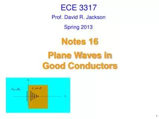
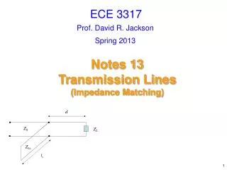
ECE 3317 Prof. David R. Jackson Spring 2013 Notes 13 Transmission Lines(Impedance Matching)
Smith Chart S Zg Z0 Sinusoidal source ZL z = 0 z Impedance matching is very important to avoid reflected power, which causes a loss of efficiency and interference. • We will discuss two methods: • Quarter-wave transformer • Single-stub matching
Quarter-Wave Transformer Z0 Z0T ZL = RL Zin Quarter-Wave Transformer: First consider a real load. Hence
Quarter-Wave Transformer (cont.) Z0 Z0T ZL = RL Zin Example: Set Hence This gives us
Quarter-Wave Transformer (cont.) Z0 Z0T YL = 1 / ZL Next, consider a general (complex) load impedance ZL. Shunt (parallel) susceptance Bs = -BL New model: YLTOT= GL Z0 Z0T ZLTOT= 1 / GL (real)
Quarter-Wave Transformer (cont.) Z0 Z0T YL = GL + j BL Ys = jBs Summary of quarter-wave transformer matching method
Quarter-Wave Transformer (cont.) Z0 Z0T YL = GL + j BL Bs = -BL Z0s ls Realization using a shorted stub (An open-circuited stub could also be used.)
Quarter-Wave Transformer with Extension Z0 Z0T Z0 ZL Zin(-d) • We choose the length d to make the input impedance Zin (-d) real. • We then use a quarter-wave transform to change the impedance to Z0.
Quarter-Wave Transformer with Extension (cont.) Example Z0 Z0T Z0 ZL
Quarter-Wave Transformer with Extension (cont.) Wavelengths towards generator
Single-Stub Matching A susceptance is added at a distance d from the load. d ZL Y0 = 1 / Z0 1) We choose the distance d so that at this distance from the load (i.e., Gin = Y0) 2) We then choose the shunt susceptance so that
Single-Stub Matching (cont.) d ZL Y0 The feeding transmission line on the left sees a perfect match.
Single-Stub Matching (cont.) d Z0 ZL Z0s ls Realization using a shorted stub (An open-circuited stub could also be used.)
Single-Stub Matching (cont.) d Z0 ZL Z0s ls We use the Smith chart as an admittance calculator to determine the distance d. • Convert the load impedance to a load admittance YL. • Determine the distance d to make the normalized input conductance equal to 1.0. • Determine the required value of Bs to cancel Bin. • If desired, we can also use the Smith chart to find the stub length ls.
Single-Stub Matching (cont.) d Z0 ZL Z0s ls Example
Single-Stub Matching (cont.) Use this one X X X X Smith chart scale: Wavelengths toward load Wavelengths toward generator
Single-Stub Matching (cont.) Next, we find the length of the short-circuited stub: Rotate clockwise from S/C to desired Bs value. Assume Z0s = Z0 Otherwise, we have to be careful with the normalization (see the note below). 0+j1 0+j2 0+j0.5 0+j0 0-j0.5 0-j2 Note: In general, 0-j1 Admittance chart
Single-Stub Matching (cont.) From the Smith chart: Admittance chart Analytically: X
Single-Stub Matching (cont.) UNMATCHED ZL z 1.62 1.55 1.0 0.78 0.38 z X Crank diagram
Single-Stub Matching (cont.) 1.62 UNMATCHED 1.55 1.0 ZL 0.78 0.38 SWR = 4.26 z z MATCHED 1.62 1.55 SWR = 1.0 ZL jBs 0.78 z z