Download
1 / 62
650 likes | 944 Vues
20th Annual Workshop on Interconnections within High Speed Digital Systems, Santa Fe, New Mexico, 3 – 6 May 2009. THz Transistors, sub-mm-wave ICs, mm-wave Systems. Mark Rodwell University of California, Santa Barbara. rodwell@ece.ucsb.edu 805-893-3244, 805-893-5705 fax.

E N D
20th Annual Workshop on Interconnections within High Speed Digital Systems, Santa Fe, New Mexico, 3 – 6 May 2009 THz Transistors, sub-mm-wave ICs, mm-wave Systems Mark Rodwell University of California, Santa Barbara rodwell@ece.ucsb.edu 805-893-3244, 805-893-5705 fax
The End (of Moore's Law) is Near (?) It's a great time to be working on electronics ! Things to work on: InP transistors: extend to 3-4 THz→ GHz & low-THz ICs GaN HEMTs: powerful transmitters from 1-300 GHz Si MOSFETs: scale them past 16 nm III-V MOSFETs: help keep VLSI scaling (maybe) VLSI transistors: subvert Boltzmann→ solve power crisis mm-wave VLSI: massively complex ICs to re-invent radio Our focus today: THz transistors - how and why
Why Build THz Transistors ? 500 GHz digital logic→ fiber optics THz amplifiers→ THz radios→ imaging, sensing, communications precision analog design at microwave frequencies→ high-performance receivers Higher-Resolution Microwave ADCs, DACs, DDSs
What Would You Do With a THz Transistor ? 640 Gb/s ETDM optical fiber links 300-1000 GHz imaging systems mm-wave communication links
Mark Rosker IEEE IMS 2007 At High Frequencies The Atmosphere Is Opaque
What Else Would You Do With a THz Transistor ? precision, high-performance analog microwave circuits higher-resolution microwave ADCs, DACs, DDSs
Simple Device Physics: Resistance bulk resistance contact resistance-perpendicular contact resistance- parallel Good approximation for contactwidths less than 2 transfer lengths.
Simple Device Physics: Depletion Layers capacitance transit time space-chargelimited current
Simple Device Physics: Thermal Resistance Exact Long, Narrow Stripe Carslaw & Jaeger 1959 HBT Emitter, FET Gate Square ( L by L ) IC on heat sink
Simple Device Physics: Fringing Capacitance wiring capacitance FET parasitic capacitances VLSI power-delay limits FET scaling constraints
Frequency Limitsand Scaling Laws of (most) Electron Devices PIN photodiode To double bandwidth, reduce thicknesses 2:1 Improve contacts 4:1 reduce width 4:1, keep constant length increase current density 4:1
Bipolar Transistor Scaling Laws Changes required to double transistor bandwidth: Linewidths scale as the inverse square of bandwidth because thermal constraints dominate.
FET Scaling Laws Changes required to double transistor bandwidth: Linewidths scale as the inverse of bandwidth because fringing capacitance does not scale.
Thermal Resistance Scaling : Transistor, Substrate, Package Probable best solution: Thermal Vias ~500 nm below InP subcollector ...over full active IC area.
THz & nm Transistors: it's all about the interfaces Metal-semiconductor interfaces (Ohmic contacts):very low resistivity Dielectric-semiconductor interfaces (Gate dielectrics):very high capacitance density Transistor & IC thermal resistivity.
industry university→industry university2007-9 appearsfeasible maybe InP Bipolar Transistor Scaling Roadmap emitter 512 256 128 64 32 nm width16 8 4 2 1 m2 access r base 300 175 120 60 30 nm contact width, 20 10 5 2.5 1.25 m2 contact r collector 150 106 75 53 37.5 nm thick, 4.5 9 18 36 72 mA/m2 current density 4.9 4 3.3 2.75 2-2.5 V, breakdown ft 370 520 730 1000 1400 GHz fmax 490 850 1300 2000 2800 GHz power amplifiers 245 430 660 1000 1400 GHz digital 2:1 divider 150 240 330 480 660 GHz
512 nm InP DHBT 500 nm mesa HBT 150 GHz M/S latches 175 GHz amplifiers LaboratoryTechnology UCSB / Teledyne / GCS UCSB 500 nm sidewall HBT DDS IC: 4500 HBTs 20-40 GHz op-amps Production ( Teledyne ) Z. GriffithM. UrteagaP. RowellD. PiersonB. BrarV. Paidi Teledyne Teledyne / BAE Teledyne / UCSB 20 GHz clock f = 405 GHz fmax = 392 GHz Vbr, ceo = 4 V 53-56 dBm OIP3 @ 2 GHzwith 1 W dissipation
150 nm thick collector 256 nm GenerationInP DHBT 70 nm thick collector 324 GHzAmplifier 60 nm thick collector 200 GHz master-slavelatch design Z. Griffith, E. Lind J. Hacker, M. Jones
324 GHz Medium Power Amplifiers in 256 nm HBT ICs designed by Jon Hacker / Teledyne Teledyne 256 nm process flow- Hacker et al, 2008 IEEE MTT-S ~2 mW saturated output power
industry university→industry university2007-9 appearsfeasible maybe InP Bipolar Transistor Scaling Roadmap emitter 512 256 128 64 32 nm width16 8 4 2 1 m2 access r base 300 175 120 60 30 nm contact width, 20 10 5 2.5 1.25 m2 contact r collector 150 106 75 53 37.5 nm thick, 4.5 9 18 36 72 mA/m2 current density 4.9 4 3.3 2.75 2-2.5 V, breakdown ft 370 520 730 1000 1400 GHz fmax 490 850 1300 2000 2800 GHz power amplifiers 245 430 660 1000 1400 GHz digital 2:1 divider 150 240 330 480 660 GHz
Conventional ex-situ contacts are a mess THz transistor bandwidths: very low-resistivity contacts are required with surface oxide with metal penetration textbook contact Interface barrier → resistance Further intermixing during high-current operation → degradation
Ohmic Contacts Good Enough for 3 THz Transistors 64 nm (2.0 THz) HBT needs ~ 2 - μm2 contact resistivities 32 nm (2.8 THz) HBT needs ~ 1 - μm2 Contacts to N-InGaAs*:Mo MBE in-situ 2.2 (+/- 0.5) - μm2 TiW ex-situ ~2.2 - μm2 Contacts to P-InGaAs:Mo MBE in-situ below 2.5 - μm2 Pd/... ex-situ ~1 (+/- ?) - μm2 *measured emitter resistance remains higher than that of contacts.
Process Must Change Greatly for 128 / 64 / 32 nm Nodes control undercut→ thinner emitter thinner emitter→ thinner base metal thinner base metal→ excess base metal resistance Undercutting of emitter ends {101}A planes: fast {111}A planes: slow
128 / 64 nm process: where we are going Developing scalable self-aligned base process 0.3 W-mm2 resistivity emitter contacts- in-situ, in MBE 2 W-mm2 resistivity base contacts- in-situ, in MBE target ~2000 GHz device
THz Field-Effect Transistors (THz HEMTs)
FET Scaling Laws Changes required to double transistor bandwidth: InGaAs HEMTs are best for mm-wave low-noise receivers......but there are difficulties in improving them further.
Gate Source Drain Why HEMTs are Hard to Improve 1st challenge with HEMTs: reducing access resistance low electron density under gate recess→ limits current gate barrier lies under S/D contacts → resistance gate barrier channel K Shinohara 2nd challenge with HEMTs: low gate barrier high tunneling currents with thin barrier high emission currents with high electron density III-V MOSFETs do not face these scaling challenges
III-V MOSFETs for VLSI→ Also Helps HEMT Development What is it ?MOSFET with an InGaAs channel Why do it ?low electron effective mass→ higher electron velocity more current, less charge at a given insulator thickness & gate lengthvery low access resistance What are the problems ?low electron effective mass→ constraints on scaling !must grow high-K on InGaAs, must grow InGaAs on Si
Wistey Singisetti BurekLee . Rodwell Gossard III-V MOSFETs in Development top of gate gate side of gate Mo S/D metalwith N+ InAsunderneath Mo S/D metal with N+ InAs underneath InAsregrowth
III-V MOSFETs as a Scaling Path for THz HEMTs Why ?Much lower access resistance in S/D regions Higher gate barrier→ higher feasible electron density in channelHigher gate barrier→ gate dielectric can be made thinner Estimated Performance (?)2 THz cutoff frequencies at 32 nm gate length
Applications of THz III-V Transistors
What Else Would You Do With a THz Transistor ? precision, high-performance analog microwave circuits higher-resolution microwave ADCs, DACs, DDSs
linear response increasing feedback output power, dBm 2-tone intermodulation input power, dBm mm-wave Op-Amps for Linear Microwave Amplification DARPA / UCSB / Teledyne FLARE: Griffith & Urteaga Reduce distortion with strong negative feedback 300 GHz / 4 V InP HBT R. Eden measured 20-40 GHz bandwidth measured 54 dBm OIP3 @ 2 GHz new designs in fabrication simulated 56 dBm OIP3 @ 2 GHz
What Would You Do With a THz Transistor ? 640 Gb/s ETDM optical fiber links 300-1000 GHz imaging systems mm-wave communication links
670 GHz Transceiver Simulations in 128 nm InP HBT transmitter exciter Simulations @ 670 GHz (128 nm HBT) LNA: 9.5 dB Fmin at 670 GHz PA: 9.1 dBm Pout at 670 GHz receiver VCO:-50 dBc (1 Hz) @ 100 Hz offsetat 620 GHz (phase 1) 3-layer thin-film THz interconnects thick-substrate--> high-Q TMIC thin -> high-density digital Dynamic divider:novel design,simulates to 950 GHz Mixer: 10.4 dB noise figure11.9 dB gain
What Would You Do With a THz Transistor ? 640 Gb/s ETDM optical fiber links 300-1000 GHz imaging systems mm-wave communication links
150 & 250 GHz Bands for 100 Gb/s Radio ? Wiltse, 1997IEEE APS-Symposium, sealevel 4 km 9 km 125-150 GHz, 200-300 GHz: enough bandwidth for 100 Gb/s QPSK 150 GHz carrier, 100 Gbs/s QPSK radio: 30 cm antennas, 10 dBm power, fair weather→ 1 km range 150 GHz band: Expect ~10-20 dB/km attenuation for rain 300 GHz band: expect ~20-30 db/km from 90% humidity
Interconnects within high-speed ICs
kz -V 0V +V 0V Slot mode CPW has parasitic modes, coupling from poor ground plane integrity +V 0V +V +V +V 0V 0V 0V Substrate modes CPW mode Microstrip mode ground straps suppress slot mode, but multiple ground breaks in complex ICs produce ground return inductanceground vias suppress microstrip mode, wafer thinning suppresses substrate modes Microstrip has high via inductance, has mode coupling unless substrate is thin. kz We prefer (credit to NTT) thin-film microstrip wiring, inverted is best for complex ICs M. Urteaga, Z. Griffith, S. Krishnan
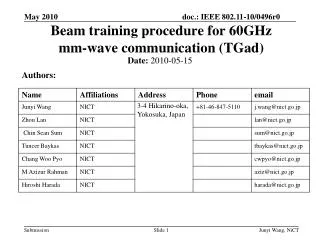
mm-wave MIMO: → Wireless Links at 100's of Gb/s
mm-wave (60-80 GHz) MIMO → wireless at 40+ Gb/s rates ? 70 GHz, 1 km, 16 elements, 2 polarizations, 3.6 x 3.6 meter array, 2.5 GBaud QPSK → 160 Gb/s digital radio ?