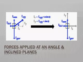
01 - Applied Forces
01 - Applied Forces. The intent of this presentation is to present enough information to provide the reader with a fundamental knowledge of mechanical applied forces used within Michelin and to better understand basic system and equipment operations. 01 - Applied Forces. Module 1 – Levers


01 - Applied Forces
E N D
Presentation Transcript
The intent of this presentation is to present enough information to provide the reader with a fundamental knowledge of mechanical applied forces used within Michelin and to better understand basic system and equipment operations.
01 - Applied Forces Module 1 – Levers Module 2 – Torque Module 3 – Sling Angles
Module 1: Levers Module 1 Levers
Module 1: Levers Categories of Levers Class 1 Lever A lever is considered a simple machine. In its most elementary form a lever is a rigid bar that rotates around a pivot point. This pivot point is called the fulcrum. An object being moved by a lever is called the load. The closer the load is to the fulcrum, the easier it is to move. In the above figure, at one end of the lever we have the effort force F1; at the other end the resistance force F2. The fulcrum is between F1 and F2 resulting in a class 1 lever. Some other examples of class 1 levers are seesaws, claw hammers, pliers, scissors, and oars.
Module 1: Levers Categories of Levers Class 1 Lever Both F1 and F2 tend to turn the lever around the fulcrum in opposite directions. The tendency to revolve the lever is called Moment of Force or Torque. The moment of force is equal to the force multiplied by its distance from the fulcrum. Moment of Effort = F1 x D1 Moment of Resistance = F2 x D2 The lever is balanced or in equilibrium when; The moment of effort = the moment of resistance F1 x D1 = F2 x D2 The mechanical advantage (MA) of a lever is the ratio of the output force to the input force F2/F1. If we want a mechanical advantage in force, D1 must be greater than D2. When using levers, if we reduce effort, we increase effort distance; and if effort required increases, we decrease effort distance.
Module 1: Levers Categories of Levers Class 2 Lever In a class 2 lever the effort force, F1 is located to one end of the bar, the resistance force, F2 is located between F1 and the fulcrum, and the fulcrum is located on the end of the bar opposite to F1. Some examples of class 2 levers are wheelbarrows and nutcrackers.
Module 1: Levers Categories of Levers Class 3 Lever In a class 3 lever the effort force, F1 is located between the resistance force, F2 and the fulcrum. Notice that for this class of lever, the effort force is greater than the resistance force. This is different from the first-class and second-class levers. However, also notice that the effort force moves through a shorter distance than the resistance force. Some examples of class 3 levers are human arm, tweezers and boom crane (cherry picker). Note: The distance is always measured to the fulcrum.
Module 1: Levers Categories of Levers Example: How much effort F1 is needed to hold a 750 lb. Crate in the shown position? F1 x D1 = F2 x D2 F1 x 6yds. = 750lbs. x 1yd. 6yds.(F1) = 750yd-lbs. F1 = 750yd-lbs. 6yds. F1 = 125lbs. MA = F2/F1 MA = 750lbs./125lbs. MA = 6
Module 1: Levers Solve the following exercises showing all calculations. 1).
Module 1: Levers Solve the following exercises showing all calculations. 2).
Module 1: Levers Solve the following exercises showing all calculations. 3).
Module 1: Levers Solve the following exercises showing all calculations. 4).
Module 1: Levers This Concludes Module 1 Levers
Module 2: Torque Module 2 Torque
Module 2: Torque Units of Torque The symbol for torque is τ. The concept of torque, also called a moment of force or couple, originated with the work of Archimedes on levers. A force applied to a lever, multiplied by its distance from the lever's fulcrum, is the torque applied at that point. Torque is a force that tends to rotate or turn things around a pivot point. Basically, torque can be thought of as rotational force or a turning or twisting force. You generate a torque any time you apply a force using a wrench. Tightening the lug nuts on your wheels is a good example. When you use a wrench, you apply a force to the handle. This force creates a torque at the center of the lug nut, which tends to turn the lug nut.
Module 2: Torque Units of Torque The force applied to a lever, multiplied by its distance from the lever's fulcrum, is torque. As a formula, you can define Torque as : Torque = Force x Distance Another way of expressing the above equation is; torque is the product of the magnitude of force and the perpendicular distance from the force to the axis of rotation (i.e. the pivot point).
Module 2: Torque Units of Torque The common values used to establish torque are force and distance. The common units used to express force are; pounds (lbs) in the U.S., newtons (N) in the ISO system. Sometimes kilograms (kg) are also used in the place of newtons as a more practical unit. The common units used to express distance are; inches (in) or feet (ft) in the U.S., meters (m) in the ISO system. Common examples of those values are listed below; U.S. examples ISO examples T = F x D T = F x D T = F x D T = F x D lbs-in = lbs x in ; lbs-ft = lbs x ft Nm = N x m; kgm= kg x m
Module 2: Torque Torque and Speed Relations In machine design it is often necessary to incorporate a power transmission device between an energy source and the desired output motion. Examples of power transmission devices may include (but are not limited to); gear trains, friction drives, timing belts, flat belts, chain & sprocket drives, levers, and screw drives. The Power Transmission device will often include a ratio or mechanical advantage aspect. A ratio can increase the output torque and decrease output speed of a mechanism, or decrease output torque and increase output speed, but not both in the same direction. A classical example is the gears on a multi-speed bicycle. Choosing a low gear that allows you to pedal easily up hill, but with a lower bicycle speed. Conversely a high gear provides a higher bicycle speed, but more torque is required to turn the crank arm of the pedal. This tradeoff is fundamentally due to the law of energy conservation and is the key concept of mechanical advantage. With a given power source you can either achieve high speed (rpm) output or high force/torque output but not both.
Module 2: Torque Torque and Speed Relations To understand the relationship between speed and torque better you have to back-up to a point of understanding the basics behind the transfer of rotation within a power transmission device. A pair of gears, in mesh, would be the simplest approach to explain the principles. Although we are using a pair of gears in mesh, these basic principles still apply to virtually all power transmission devices. When two gears are in mesh a ratio is formed. That ratio is determined by the distances from the center of the gear to the point of contact, or in other words the radius of the gear. For instance, in a device with two gears, if one gear is twice the diameter of the other, the ratio would be 2:1. This ratio would be consistent in the fact that it applies to most aspects of the gear train. The diameters would be a 2:1 ratio, the circumference would be 2:1, the number of teeth (if it is a gear train) would be 2:1, as well as the radii as illustrated in figure below.
Module 2: Torque Torque and Speed Relations For the purposes of this illustration we’ll assume the fact that in the figure at right, Gear 2 has a 2:1 ratio with Gear 1. In this figure, you can see that the radius of Gear 1 is smaller than Gear 2. Establishing the fact that the smaller gear is spinning twice as fast as the larger gear, because the circumference has to travel twice as far for every revolution of the larger gear. The same is true for the larger gear, it is spinning at half the speed of the smaller gear, because the circumference only travels half as far for every revolution of the smaller gear. The fact that one gear is spinning faster or the fact that one gear is spinning half as fast as the other is because of the ratio between the gears; the gear ratio. If both gears had a 1:1 ratio, all aspects would be equal and they would rotate at the same speed. The same would be true when a comparison of speed and torque is used. Speed (rpm) represents how fast the gears are spinning, where torque represents how much force the rotating gear is capable of supplying at the center of the axle or shaft. Remember, torque is a product of force and distance.
Module 2: Torque • Conversely, if Gear 2 is the input and Gear 1 is the output: • The output speed (rpm) will be twice the input speed (rpm). • The output torque will be half that of the input. Torque and Speed Relations Using the same previous example in figure above, an example of 2:1 ratio between the gears, the speed (rpm) will be cut in half, but the torque will be doubled from Gear 1 to Gear 2. Inversely the speed (rpm) will double, but the torque will be cut in half from Gear 2 to Gear 1. Simply because the amount of force transmitted from one gear to another stays the same no matter how many gears are utilized. When the force is applied at the point of tooth contact between both gears (in mesh) the force is then transmitted thru the radius and is multiplied by the distance to the center of the axle or shaft. Much like the results of the action of a lever shown in figure below. Thus if Gear 1 is the input and Gear 2 is the output: The output speed (rpm) will be half the input speed (rpm). The output torque will be twice that of the input. With that known, we can establish the relationship between torque and speed. Torque is inversely proportional to speed (rpm). In other words, there is a trade-offbetween how much torque a motor delivers, and how fast the shaft spins.
Module 2: Torque Torque and Speed Relations The relationship of torque and speed (rpm) is the ratio that is established between the common power transmission devices, such as a gear train, chain & sprocket drive, belt drive system, or friction drive system.
Module 2: Torque Calculation Exercises 1). With a F = 180 lbs (800.68 N) and D = 10 in (0.25 m) find the torque. 2). If a torque of 325 lb-ft (440.64 N-m) is required at a distance of D = 15 in (0.38 m), what would the F be? 3). If F = 150 lbs (667.23 N) and the torque must be 900 lb-ft (1220.24 N-m), what would the D be equal to? 4). Torque = 1100 lbs-ft (1491.4 N-m) and D = 1 ft (0.305 m), find the F. 5). Torque = 300 lb-ft (406.75N-m), and F = 135 lbs (600.51 N), find the D.
Module 2: Torque Calculation Exercises Metric Example: We have a motor capable of producing 10 N-m of torque. Attached to the motor is a gear with a PCD of 200 driving a gear with a PCD of 400. What is the torque exerted on the shaft of the driven gear? Given: PCD gear #1 = 200 PCD gear #2 = 400 Motor torque = 10 N-m Find: Torque on shaft of gear #2 Step 1 : Find the force (F1) at the edge of gear #1. T= F1 x D F1 = 100 N Step 2 : Find the torque on gear/shaft #2. T = F1 x DT= 100 N x 0.2 m
Module 2: Torque Calculation Exercises American Example: Given: PCD gear #1 = 1.97 in. Find: F1 ; F2 PCD gear #2 = 5.91 in. PCD gear #3 = 3.54 in. Torque on shaft of gear # 2 Motor torque = 36.88 Lb-ftTorque on shaft of gear # 3 Step 1 - Solve F1: = 449.76 Lbs. Step 2 - Solve T2: T2 = F1 x D2 T2 = 449.76 Lbs x 0.246 ft T2 = 110.64 Lb-ft Step 3 - Solve F2: = 449.76 Lbs. Step 4 - Solve T3: T3 = F2 x D3 T3 = 449.76 Lbs. x 0.147 ft T3 = 66.11 Lb-ft
Module 2: Torque Calculation Exercises American Example: Conclusion: F1 = F2 The input force on a gear equals the output force on a gear. The torque transmitted to the shaft through the gear is directly proportional to the PCD of the gear. What would F3 be? ……………
Module 2: Torque Calculation Exercises 1). Given:PCDgear #1 = 7.87 in.(200mm) Find: F1___________ PCD gear #2 = 11.81 in.(300mm) F2___________ PCD gear #3 = 3.94 in.(100 mm) F3___________ Motor torque = 11.06 Lb-ft (15 N-m) Torque on shaft of gear # 2_______ Torque on shaft of gear # 3_______
Module 2: Torque Calculation Exercises 2). Given: PCD gear #1 = 11.81 in.(300mm) Find: Torque on shaft 1 __________ PCD gear #2 = 9.84 in.(250mm) Torque on shaft 2 __________ PCD gear #3 = 3.54 in.(90mm) Torque on shaft 3 __________ F3 (Load) = 992.08 Lbsf (450 kgf) F2 _______ L (Length) = 15.75 in. (400mm) F1 to hold load stationary _______
Module 2: Torque Calculation Exercises 3). Given:PCDgear #1 = 14.53 in.(369mm) Find: Torque on shaft of Sprocket A PCD gear #2 = 7.80 in.(198mm) PCD Sprocket B = 3.94 in.(100mm) PCD Sprocket A = 8.19 in.(208mm) Motor output = 14.75 Lb-ft (20 N-m)
Module 2: Torque Calculation Exercises 4). A 12mm screw has a recommended torque value of 9.7 kg-m and will snap at 5 times this value. If a 185 lb. mechanic hangs on the end of a wrench 14 inches long will the screw break? CHALLENGE PROBLEM: 5). A mechanic needs to torque a mounting bolt (18mm, quality 8.8) to 225 lb-ft. to secure the assembly to the base. Using an 18 in. long torque wrench, a 4X torque multiplier, and a 1 ft. extension handle, can the mechanic torque this bolt to the correct value? NOTES: The mechanic can generate 75 N-m of torque on a 39 in. torque wrench The extension handle covers 152.4 mm of the torque wrench handle
Module 2: Torque This Concludes Module 2 Torque
Module 3: Sling Angles Module 3 Sling Angles
Module 3: Sling Angles Slings A 1200 pound load is being lifted by wire ropes. The top rope represents a point upon which forces act in a static system. Forces F2 and F3 are angular forces that realize both horizontal and vertical forces. We call these resultant forces.
Module 3: Sling Angles Slings Laws of physics say that the total vertical downward forces must equal the total of vertical upward forces. In this example: F1 = F2 + F3
Module 3: Sling Angles Slings Let’s look closer at F3 resultant. Laws of physics also say that any resultant (angular) force can be divided into horizontal and vertical components. Therefore, f3 resultant can be divided into F3 vertical and F3 horizontal. Finding F3 resultant now becomes a simple matter of solving a right triangle.
Module 3: Sling Angles Slings If we know the vertical force of one sling (F3 vertical) to be 600 pounds and angle A to be 80 degrees, the following is true. Therefore: Cosine angle A /2 = Cosine 40 deg. = F3r = F3r = 783.24 lbs.
Module 3: Sling Angles Slings What happens if we change angle A to 160 degrees? Cosine 80 deg. = F3r= F3r= 3455.27 lbs.
Module 3: Sling Angles Slings 1) Determine the tension in each sling.
Module 3: Sling Angles Slings 2) Determine the tension in each sling.
Module 3: Sling Angles Slings 3) Determine the tension in each wire supporting the traffic light.
Module 3: Sling Angles Slings 4) Determine the included angle between the ropes. The tension on each rope is 900 lbs.
Module 3: Sling Angles Slings 5) Determine the tension in each of the 4 slings supporting the load.
Module 3: Sling Angles This Concludes Module 3 Sling Angles