FPGA and CADs
FPGA and CADs. Presented by Peng Du & Xiaojun Bao. INRTODUCTION. The History of Programmable Logic. Highest Density FPGAs in The Industry Up to XC2V8000 (8 million systems gates, 104,832LCs) Up to 1108 user I/O’s in the most advance package offering (FG1152, and FG1517.

FPGA and CADs
E N D
Presentation Transcript
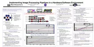
FPGA and CADs Presented by Peng Du & Xiaojun Bao
INRTODUCTION The History of Programmable Logic
Highest Density FPGAs in The Industry • Up to XC2V8000 (8 million systems gates, 104,832LCs) • Up to 1108 user I/O’s in the most advance package offering (FG1152, and FG1517 Virtex-II Platform FPGA from Xilinx
FPGA Programming Technologies • SRAM Programming Technology Anti-fuse Programming Technology Erasable Programming Technology
FPGA Architecture All FPGAs are composed of three fundamental components: Logic blocks I/O blocks Programmable routing
A Generic FPGA I/O block Programmable routing Logic block
FPGA Logic Block Architecture Look-up Table (LUTs) The logic block used in an FPGA strongly influences the FPGA speed and area-efficiency. While many different logic blocks have been used in FPGAs, most current commercial FPGAs use logic blocks based on:
Number of Blocks and Block Area 800 50 Number of Blocks Block Area 700 30 600 500 10 3 4 5 6 7 2 Number of inputs
FPGA Routing Architecture Commercial FPGAs can be classified into the four groups, based on their routing architecture. • Island – Style FPGA • Row – Based FPGA • Sea – Gates FPGA • Hierarchical FPGA
Advantages and Disadvantages of SRAM Programming • The major advantage of this technology is that FPGA can be reconfigured (in-circuit) very quickly and can be produced using a standard CMOS process technology. • The chip area required by SRAM approach is relatively large.
Anti-fuse Programming Technology An anti-fused normally presents a high-impedance state but can be “fused” into a low-impedance state when programmed by a high voltage. The anti-fuse used in each of FPGAs from different company differs in construction . But their function is the same.
Advantages and Disadvantages of Anti-fuse Programming • Anti-fuses chip area are small and Anti-fuses have a significantly lower on resistance and parasitic capacitance than transistors, reducing RC delays in the routing. • The major disadvantages of anti-fuses is that their manufacture requires modifications to the basic CMOS process.
Introduction This technology is the same as that used in EPROM and EEPROM memories.
Advantages and Disadvantages of EPROM and EEPROM Programming • The major advantage of EPROM is that it requires re-programmable but do not require external storage. EEPROM can be re-programmed in-circuit. • A disadvantage of EPROM is that the resistor consumes static power. And EEPROM requires more chip area and multiple voltage sources.