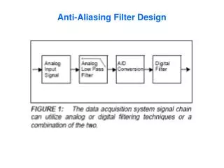
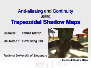
Anti-aliasing and Continuity using Trapezoidal Shadow Maps
Anti-aliasing and Continuity using Trapezoidal Shadow Maps. Speaker: Tobias Martin Co-Author: Tiow-Seng Tan National University of Singapore. Standard Shadow Maps. Content. Shadows in Computer Graphics Standard Shadow Maps (SSM) Problems with SSM Problem #1: Aliasing/Resolution

Anti-aliasing and Continuity using Trapezoidal Shadow Maps
E N D
Presentation Transcript
Anti-aliasing and ContinuityusingTrapezoidal Shadow Maps Speaker: Tobias Martin Co-Author: Tiow-Seng Tan National University of Singapore Standard Shadow Maps
Content • Shadows in Computer Graphics • Standard Shadow Maps (SSM) • Problems with SSM • Problem #1: Aliasing/Resolution • Problem #2: Polygon Offset • Problem #3: Continuity • Trapezoidal Shadow Maps • Conclusion
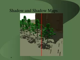
Shadows in Computer Graphics • Why? • Spatial relationship between objects is better perceivable • Realism is enhanced • Our Requirements: • Robust shadows in real-time (Screenshots taken from “shadowcast.exe” by Mark J. Kilgard, NVIDIA)
Standard Shadow Maps (SSM) 1. Shadow Map Generation: • Transform scene into post-perspective space (PPS) of light, i.e.:vL = PL · CL· W · v • Render scene from this space • Copy depth buffer into shadow map 2. Shadow Determination: • Render scene in eye’s PPS and perform shadow test per-fragment • Fragment is in shadow iff zp > shadowmap[xp, yp], where xp,yp and zp is fragment in PPS of light (Screenshots taken from “shadowcast.exe” by Mark J. Kilgard, NVIDIA)
Standard Shadow Maps (SSM) • Problem #1:Resolution ProblemJagged shadow boundary appears due to low resolution in shadow map Trivial solution:Increase shadow map size to increase resolution & improve quality
Standard Shadow Maps (SSM) • Problem #2:Polygon OffsetDue to finite precision, surfaces can cast wrong shadows on themselves Practical Solution: Adding offset to depth values to move shadow slightly away from light
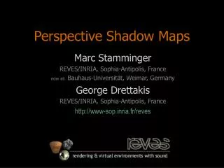
Current Solutions • Problem #3: Continuity (1) • Straightforward approximation can result in shadow discontinuities e.g. in Perspective Shadow Maps (PSM)[Stamminger and Drettakis 2002] e.g. in the Bounding Box Approximation (BB) [Brabec et al. 2002] Frame i +1 Frame i
Current Solutions • Problem #3: Continuity (2) • What happens if shadow map depends on dynamic scene geometry? light light scene’s bounding box eye eye scene’s bounding box n frames later ”expanded” hull contains shadow occluders shadow map quality worsened ”tight” hull contains shadow occluders good shadow map quality
Trapezoidal Shadow Maps (TSM) • Solution to Problem #1 (Resolution) • Shadow map generation focuses on area potentially visible to the eye • Solution to Problem #2 (Polygon Offset) • Depth values are preserved, so that problem is not worsened • Solution to Problem #3 (Continuity) • Frame coherent technique resulting in a continuous change in shadow map resolution
Trapezoidal Shadow Maps (TSM) PPSof light NT A trapezoidal space Shadow map resolution is increased Shadow aliasing is reduced
Trapezoidal Shadow Maps (TSM) • Solution to Problem #1 • SSM algorithm is slightly modified: • Calculate shadow map in the trapezoidal space, and perform the shadow test there as well, i.e.:vT = NT· PL· CL· W · v Except for the calculation of NT the algorithm can completely be mapped to graphics hardware!
Trapezoidal Shadow Maps (TSM) • Side effect of the trapezoidal transformation a) Approximation of an eye's frustum with a trapezoid b) Applying NTmay lead to severe polygon offset problems Different distribution of z-values require different offsets (a) (b) Non-uniform distribution Uniform distribution
Trapezoidal Shadow Maps (TSM) Solution to (worsened) Problem #2: • Apply NT only to the x- and y-values • Maintain z in PPS of light: Store (xT , yT , zL) in the shadow map Applying modifiedNT Simply applyingNT
Trapezoidal Shadow Maps (TSM) • 1st pass (Shadow Map Generation) • Vertex stage: • vT = NT· PL· CL· W · v • vL = PL· CL· W · v • Fragment stage: • shadowmap[xT, yT]= zL instead of zT Use additional texture coordinate vL and replace zT with zL per fragment
Trapezoidal Shadow Maps (TSM) • 2nd pass (Shadow Determination) • Vertex stage: • vE = PE· CE· W · v • vT = NT· PL· CL· W · v • vL = PL· CL· W · v • Fragment stage: • Fragment in shadow iff zL > shadowmap[xT, yT] Use additional texture coordinate vL and use zL for shadow map comparison
Trapezoidal Shadow Maps (TSM) Solution to Problem #3 • Base and Top Lines: Center Line 2D-Convex Hull Base & Top Line l lt lb CHE • Center line governs the choices of top and base line top and base line transit smoothly from frame to frame
Trapezoidal Shadow Maps (TSM) • Side Lines: 80% rule governs the choices 0% Focus region of the eye 80% line Trapezoidal approximation in L Trapezoidal space due to 80% rule
Trapezoidal Shadow Maps (TSM) q • Calculate NT that pL is mapped to 80% line in T • Calculate q using 1D perspective projection map to y=+1 lt map to y= ` pL map to y=-1 E lb l • (Minus signs in the proceedings got eaten up by the printer)
Trapezoidal Shadow Maps (TSM) • Indication for Continuity • Plot of the total area covered by focus region in shadow map • Change in frustum are color encoded
Trapezoidal Shadow Maps (TSM) light light light • General case: • Eye’s frustum E is not completely within then light’s frustum L • Algorithm can be easily adjusted • Singularities are avoided eye eye eye
Results • Fantasy World: • BB vs. PSM vs. TSM Urban Model: • PSM vs. TSM
Conclusion • TSM addresses • Resolution Problem • Polygon Offset Problem • Continuity Problem • …following the 3 principles • Effectiveness of 80% rule • Simplicity which is difficult to achieve • Continuity rather than “correctness” • Q and A TSM http://www.comp.nus.edu.sg/~tants/tsm.html
Literature BRABEC, S., ANNEN T., AND SEIDEL, H. 2002. Practical Shadow Mapping. Journal of Graphics Tools 7(4), 9–18. CROW, F. C. 1977. Shadow Algorithms for Computer Graphics. In Proceedings of SIGGRAPH 1977, 242–248. STAMMINGER, M., AND DRETTAKIS, G. 2002. Perspective Shadow Maps. WILLIAMS, L. 1978. Casting curved shadows on curved surfaces. In Proceedings of SIGGRAPH 1978, 270–274. WOO, A., POULIN, P., AND FOURNIER, A. 1990. A survey of shadow algorithms. IEEE Computer Graphics and Applications, 10(6), 13–32.