Download
1 / 23
230 likes | 505 Vues
Gas Power Systems -1. Air Standard Cycles The Spark Ignition Engine. Overview. Air standard cycles for reciprocating engines General operational features Indicator diagrams Spark ignition engines The Otto cycle. General classes of engines. Reciprocating internal combustion engines.

E N D
Gas Power Systems -1 Air Standard Cycles The Spark Ignition Engine
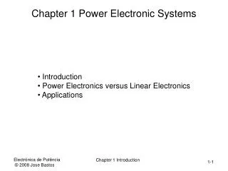
Overview • Air standard cycles for reciprocating engines • General operational features • Indicator diagrams • Spark ignition engines • The Otto cycle
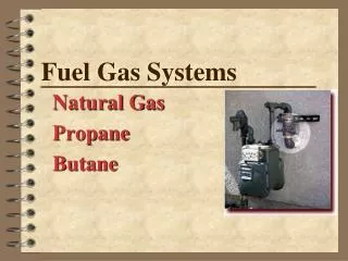
General classes of engines • Reciprocating internal combustion engines. • Reciprocating compressors • Reciprocating steam engines
Single action reciprocating engine. Single vs. double action engines Double action reciprocating engine.
An analog instrument that measures pressure vs. Displacement in a reciprocating engine. The graph is in terms of P and V. Area is proportional to the work done per cycle p V Indicator diagrams
Work per cycle is represented in terms of a mean effective pressure and the displacement. p MEP = Mean effective pressure V X = Displacement Indicator Diagrams
To compute the work per cycle, use the MEP and the displacement. Work = MEP x A x Displacement. MEP = kiY, where ki is a constant Y = the average ordinate on the indicator diagram. X = displacement A = area of cylinder heat. Indicator Diagrams
Processes: a-b Intake b-c Compression c-d Combustion (spark ignited) d-e Power Stroke e-f Gas Exhaust b-a Exhaust Stroke p d c e a b V Displacement Clearance volume Ideal indicator diagramSpark ignition engine - The Otto cycle
The air standard Otto cycle approximates the automotive internal combustion engine and aircraft engines. Assume a quasistatic process, isentropic compression, and isentropic exhaust. 4 p s = Constant 3 5 1 6 2 V The Otto cycle Displacement
s = Constant 4 T 4 p 3 3 5 5 1 6 2 6 2 s V V = Constant P-V diagram for the actual variable mass system. This is the T-s diagram for the fixed mass system. The Otto cycle
Real Process 1-2 Intake of fuel/air mixture at P1 2-3 Compression to P3 3-4 Combustion, V = cons. and increasing P 4-5 Expansion 5-6 Exhaust at constant V and falling pressure 6-1Exhaust at P1 Air Cycle Approximation (Constant mass, closed internally reversible, cycle) 2-3 Isentropic compression 3-4 Heat addition at constant volume 4-5 Isentropic expansion 5-6 Heat rejection at constant volume The air-standard Otto cycle
The reversible Otto cycle • Internally reversible processes • Constant specific heats • k = Cp/Cv = Constant • Polytropic compression and expansion, PVk = Const. • Treat air as an ideal gas.
4 T QH 3 5 QC 2 6 s V = Constant Thermodynamic analysis for the reversible Otto cycle (1)
Key assumptions: (1) Internally reversible processes (2) Constant specific heats Important consequence: (1) Efficiency is independent of working fluid (2) Efficiency independent of temperatures Thermal efficiency
Efficiency of Air Standard Otto Cycle k = 1.3 = Cp/Cv T QH 4 3 WNET 5 QC 2,6 s rv
k = 1.4 k = 1.3
4 T QH 3 5 QC 2,6 s V = Constant The Otto cycle with real gases • Variable specific heats. • Efficiency based on internal energies obtained from the gas tables which take into account variable specific heats.
Key terms and concepts Spark ignition engine Otto cycle Clearance volume Indicator diagram Indicator constant, ki Mean effective pressure Displacement