Download
1 / 33
330 likes | 358 Vues
Learn about VHDL resolution functions used to resolve signals with multiple drivers, along with examples and guidelines for implementation. Explore resolution functions for buses and handling conflicts in signal control.

E N D
Advanced topics Lecture 7
Outline • 7.1. Resolution functions • 7.2. Guarded signals. Disconnection • 7.3. GENERATE statement
Resolution functions Are used in order to resolve the value of a signal when the signal has more than one source (driver). In VHDL it is illegal if a signal with more than one driver is not resolved. The resolution function: Is written by the programmer Is called by the simulator: When at least one of the signal’s drivers has an event. The resolution function will return a value obtained from the values of all signal’s drivers. Unlike other HDLs, in VHDL do not exist predefined resolution functions.
Resolution functions • A resolution function • Has only one (input) parameter • Which is always an unconstrained array with elements having the type of the signal • And returns a single value: • The value has the same type as the signal and it is named resolved value • The input parameter is an unconstrained array because when the resolution function is written we don’t know how many drivers will have the signal when the function will be called. • For a resolved signal (declared as a resolved signal) the resolution function will be called even if the signal has a single driver.
Declaring a resolved signal A wrong example: TYPE fourval IS (X,L,H,Z); SUBTYPE fourval_rez IS frez fourval; -- frez is the resolution function -- It is wrong because the resolution function was not specified or declared. In conclusion, in order to declare a resolved signal there is a sequence that must be followed: PACKAGE frezpack IS TYPE fourval IS (X,L,H,Z); TYPE fourval_vector IS ARRAY(NATURAL RANGE<>) OF fourval; FUNCTION frez(t: fourval_vector) RETURN fourval; SUBTYPE fourval_rez IS frez fourval; END PACKAGE frezpack;
Declaring a resolved signal A resolved signal can be declared in two ways: 1. as a resolved subtype 2. by using the resolution function in the signal declaration. Example (continued): USE WORK.frezpack.ALL; ENTITY ex IS END; ARCHITECTURE resolved_e OF ex IS SIGNAL s1,s2: fourval_rez;-- first way SIGNAL s3: frez fourval;--second manner BEGIN … END ARCHITECTURE;
X The strength decreases L H Z Resolution functions : example A resolution function should be associative and commutative because its returned result should not depend on the order in which the inputs of the function (i.e., the drivers of the signal) are processed, since this order cannot be controlled by the programmer. Example of resolution function for the type fourval: The strength of the values of the type fourval: X means undefined value, Z means high impedance. L and H have equal strength. When at least one driver is L and one H, the resolution function will return X (there is a conflict).
Resolution functions : example The table that describes the behaviour of the resolution function :
Resolution functions : example The function from example: PACKAGE BODY frezpack IS FUNCTION frez(t: fourval_vector) RETURN fourval IS VARIABLE result: fourval:=Z;--it is initialized with --the weakest value of the type fourval BEGIN FOR i IN t’RANGE LOOP --t’RANGE processes the entire array t CASE t(i) IS WHEN X => result:=X; RETURN result; WHEN L=> CASE result IS WHEN X|H => result:=X; RETURN result; WHEN L|Z => result:=L; END CASE;
WHEN H=> CASE result IS WHEN X|L => result:=X; RETURN result; WHEN H|Z => result:=H; END CASE; WHEN Z => NULL;--result remains unchanged END CASE; END LOOP; RETURN result; END FUNCTION frez; END PACKAGE BODY; Remark: In this case the function could have been implemented with IF instead of CASE, but with CASE it is more general.
Resolution functions for buses • If there are several devices connected to a bus, we have to take care that a single device controls the bus at a time: • We have to treat the case when more than one device attempt to control the bus • => it is a conflict • That will be signalled by the resolution function by returning a special value “multiple drivers” • We have to treat also the case when no device controls the bus: • The resolution function will return a special value, “not driven” • A signal (device) that does not control the bus will have the value “not driven”, too. • These special values may be taken from the unused values of the bus (e.g. negative values for addresses) or • If there aren’t any unused values then • We will transform the bus type in a RECORD • We add one more fields to the bus values
Example Suppose that we have a data and address bus, and the addresses values can be only nonnegative integers, hence we can chose negative values for addresses as special values. PACKAGE busrez IS TYPE xtype IS RECORD addr: INTEGER;--has only values >=0 data: INTEGER; -- supplementary_field: INTEGER; END RECORD; CONSTANT notdriven: xtype:=(-1,-1); CONSTANT multipledrivers: xtype :=(-2,-2); TYPE xtype_vector IS ARRAY(NATURAL RANGE <>) OF xtype; FUNCTION xf(t:xtype_vector) RETURN xtype; SUBTYPE xbus IS xf xtype; END PACKAGE busrez;
PACKAGE BODY busrez IS FUNCTION xf(t:xtype_vector) RETURN xtype IS VARIABLE result: xtype:=notdriven; VARIABLE count: INTEGER:=0; BEGIN IF t’LENGTH=0 THEN --’LENGTH attribute that returns the length of an array result:=notdriven; REPORT “no driver” SEVERITY WARNING; END IF;-- this case can appear only for guarded signals, whose drivers can be --disconnected FOR i IN t’RANGE LOOP IF t(i) /= notdriven THEN count := count +1; result:=t(i); END IF;
IF count>1 THEN result:=multipledrivers; REPORT “more than one driver !” SEVERITY ERROR; RETURN result; END IF; END LOOP; IF count=0 THEN REPORT “zero drivers !” SEVERITY WARNING; END IF; RETURN result; END xf; END PACKAGE BODY busrez;
7.2. Guarded signals • Signal declaration has the following syntax: SIGNAL list_of_signals: [resolution_function] signal_type [signal_kind] [:=expression]; where signal_kind can be BUS or REGISTER • Definition: the guarded signals are special signals declared BUS or REGISTER. • Guarded signals must be resolved signals, hence they must have a resolution function. • Guarded signals may be assigned values only inside guarded blocks. • Towards guarded signals we can make: - concurrent guarded assignments or - sequential assignments, but - we CAN NOT make concurrent non-guarded assignments.
Guarded signals • Inside a guarded block, when the signal GURAD becomes FALSE, the driver of the guarded signal will be disconnected • Disconnection takes place after a time period named disconnect time. • When the guard is TRUE, the signal driver receives values according to the signal assignment statement. • In the case of an unguarded signalthat has a concurrent guarded assignment, when the guard becomes FALSE the signal driver is not disconnected, but the driver maintains the previous values, without taking into account the new values that could have been generated by the signal assignment statement (the signal driver is deactivated) • See net example. • The time after which takes place the disconnection of a driver of the guarded signal can be specified by disconnect_specification (after the signal declation): DISCONNECT name_of_guarded_signal: signal_type AFTER time_expression; • Diconnection of a driver is an event, hence the resolution function will be called.
Example ARCHITECTURE guarded_ex OF example IS SIGNAL guarded_signal: wired_or BIT REGISTER; SIGNAL unguarded_signal: wired_and BIT;-- this signal does not have to -- be resolved BEGIN b: BLOCK(guard_expression) BEGIN guarded_signal <= GUARDED expression1 AFTER time1; unguarded_signal <= GUARDED expression2 AFTER time2; END BLOCK b; END ARCHITECTURE; The example is equivalent with:
Example (cont’d) ARCHITECTURE guarded_ex OF example IS SIGNAL guarded_signal : wired_or BIT REGISTER; SIGNAL unguarded_signal : wired_and BIT;--no need to be resolved BEGIN b: BLOCK(guard_expression) BEGIN p1: PROCESS BEGIN IF GUARD THEN guarded_signal <= expression1 AFTER time1; ELSE guarded_signal <= NULL; -- is disconnected -- signal <= NULL means driver disconnection END IF; WAIT ON GUARD, signals_in_expression1; END PROCESS p1;
p2: PROCESS BEGIN IF GUARD THEN unguarded_signal <= expression2 AFTER time2; END IF; --there is no ELSE since NOTHING HAPPENS when -- GUARD = FALSE WAIT ON GUARD, signals_in_expression2; END PROCESS p2; END BLOCK b; END ARCHITECTURE;
Differences between BUS and REGISTER • Concerning the place where they can be: • Guarded BUS signals may be both: • Locally declared signals intside an architecture • Ports of an entity • Guarded REGISTER signals may be: • Only locally declared signals inside an architecture. • Concerning how the last driver is disconnected: • For a guarded BUS signal: • If all drivers are disconnected, it must be specified the value that the signal will have in this case • It means that the resolution function must specify a value for the case when all drivers are disconnected. • For a guarded REGISTER signal: • When the last driver is disconnected, the signal maintains the previous value • The resolution function is not called when the last driver is disconnected • => the resolution function doesn’t have to specify a value for this case.
Example of 4:1 multiplexer implemented with guarded signals USE WORK.my_pack.ALL; -- my pack contains the resolution function wired_or ENTITY mux IS GENERIC(mux_del: TIME:= 5ns); PORT(din: IN BIT_VECTOR(3 DOWNTO 0); sel: IN BIT_VECTOR(1 DOWNTO 0); z: OUT BIT); END mux; ARCHITECTURE with_guarded_signals OF mux IS SIGNAL temp: wired_or BIT BUS; -- in this case it can be REGISTER, as well BEGIN
b0: BLOCK (sel=“00”) BEGIN temp<= GUARDED din(0); END BLOCK b0; b1: BLOCK (sel=“01”) BEGIN temp<= GUARDED din(1); END BLOCK b1; b2: BLOCK (sel=“10”) BEGIN temp<= GUARDED din(2); END BLOCK b2; b3: BLOCK (sel=“11”) BEGIN temp<= GUARDED din(3); END BLOCK b3; z <= temp AFTER mux_del; END ARCHITECTURE; -- in this case it is not very important how is the resolution function, because -- the signal temp will have only one driver at a time, the rest of 3 drivers being -- disconnected.
It is used mostly for describing regular structures represents a conditional compiling mechanism in VHDL The syntax is: label_id: generation_scheme GENERATE concurrent_statements END GENERATE [label_id]; 7.3. GENERATE statement
GENERATE (cont’d) • The generation scheme can be of type: • FOR : the index doesn't have to be declared • IF : there is neither ELSIF nor ELSE • IF and FOR don’t have any execution semantics (nothing to do with the sequential statements IF and LOOP FOR) • Concurrent statements from the body of GENERATE are most typically (but not necessarily) component instantiation statements. • The compiler expands the code from GENERATE. • E.g., if a generation scheme of type FOR with 5 iterations is used, and if in the body of GENERATE there is a component instantiation statement, then in the expanded code there will be 5 component instantiation statements.
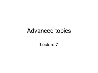
Example We model a 4 bits shift register using GENERATE. The register consists of 4 D flip-flops, like in figure 11. The D flip-flop description: ENTITY dff_1 IS GENERIC(tp: time:=1ns); PORT(d, clk, reset: IN BIT; q, qb: OUT BIT); END dff_1; ARCHITECTURE behave OF dff_1 IS BEGIN PROCESS(reset, clk, d) BEGIN IF reset='0' THEN q<='0' AFTER tp; qb<='1' AFTER tp; ELSIF(clk='1') AND clk'EVENT AND clk'LAST_VALUE='0‘ THEN
q<= d AFTER tp; qb<=NOT d AFTER tp; END IF; END PROCESS; END ARCHITECTURE; CONFIGURATION dff_cfg OF dff_1 IS FOR behave END FOR; END CONFIGURATION; -- the shift register : ENTITY shift_reg IS GENERIC(len: NATURAL:=4); PORT(reset, clock, a: IN BIT; b: OUT BIT); END shift_reg;
The shift register z(3) z(4) b z(0) z(1) z(2) a D Q Q D Q D Q D clk clk clk clk reset reset reset reset reset clock shift_reg Fig 11. The shift register realized with D flip-flops
FOR type generation scheme -- GENERATE statement with -- FOR generation scheme ARCHITECTURE shift_gen_1 OF shift_reg IS COMPONENT dff IS GENERIC(tp:TIME:=1ns); PORT(d, clk, reset: IN BIT; q, qb: OUT BIT); END COMPONENT; SIGNAL z: BIT_VECTOR(0 TO 4); BEGIN z(0)<=a; g: FOR i IN 0 TO 3 GENERATE dffx: dff PORT MAP(z(i), clock, reset, z(i+1), OPEN); END GENERATE; b<=z(4); END shift_gen_1;
GENERATE with IF and FOR generation schemes The drawback of the previous model is that, inside the GENERATE statement, the flip-flops from the edges of the shift register are not treated in the same way as those from inside of the shift register. We can give a uniform treatment if we combine the FOR and IF generation schemes: -- GENERATE with generation schemes of type FOR and IF ARCHITECTURE shift_gen_2 OF shift_reg IS COMPONENT dff IS GENERIC(tp:TIME:=1ns); PORT(d, clk, reset: IN BIT; q, qb: OUT BIT); END COMPONENT; SIGNAL z:BIT_VECTOR(1 TO len-1);
BEGIN g1: FOR i IN 0 TO (len-1) GENERATE g2: IF i=0 GENERATE dffx: dff PORT MAP(d=>a, clk=> clock, reset=>reset, q=>z(1), qb=>OPEN); END GENERATE g2; g3: IF i=(len-1) GENERATE dffx: dff PORT MAP(d=>z(len-1), clk=>clock, reset=>reset, q=>b, qb=>OPEN); END GENERATE; --g3 g4: IF (i>0) AND (i<len-1) GENERATE dffx: dff PORT MAP(z(i), clock, reset, z(i+1), OPEN); END GENERATE g4; END GENERATE; -- g1 END ARCHITECTURE shift_gen_2;
Configuration for GENERATE -- A configuration for the architecture shift_gen_2 will be: CONFIGURATION cfg_gen OF shift_reg IS FOR shift_gen_2 FOR g1 FOR g2 FOR ALL: dff USE CONFIGURATION WORK.dff_cfg; END FOR; END FOR;--g2 FOR g3 FOR ALL: dff USE ENTITY WORK.dff_1(behave); END FOR; END FOR;--g3 FOR g4 FOR ALL: dff USE ENTITY WORK.dff_1(behave); END FOR; END FOR;--g4 END FOR; -- g1 END FOR; -- shift_gen_2 END cfg_gen;
A test entity for the shift register entity test_shift_reg is end; architecture a_test of test_shift_reg is COMPONENT shift_reg IS GENERIC(len: NATURAL:=4); PORT(reset, clock, a: IN BIT; b:OUT BIT); END COMPONENT; SIGNAL insig, r, cl, outsig: BIT; BEGIN l: shift_reg PORT MAP(r, cl, insig, outsig); cl<=NOT cl AFTER 50ns; r<='1', '0' after 3ns, '1' after 40ns; insig<='1' after 145ns, '0' after 380ns, '1' after 1680ns; end;
configuration cfg_test of test_shift_reg is for a_test for l: shift_reg use configuration work.cfg_gen; end for; end for; end cfg_test;