Download
1 / 22
220 likes | 251 Vues
R&D ERL R&D: G5 test and Commissioning Plan. R&D: G5 test and Commissioning Plan. Eduard Pozdeyev, Dmitry Kayran. BNL R&D ERL Review February 17-18, 2010. Why we are doing the G5 test?. G5 test is first stage of ERL commissioning Most of all ERL components can be tested during G5Test

E N D
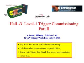
R&D ERLR&D: G5 test and Commissioning Plan R&D: G5 test and Commissioning Plan Eduard Pozdeyev, Dmitry Kayran BNL R&D ERL Review February 17-18, 2010
Why we are doing the G5 test? • G5 test is first stage of ERL commissioning • Most of all ERL components can be tested during G5Test • Will demonstrate of high brightness SRF Injector operating • The high energy at the end • We will measure: • Projected emittance in both planes • Bunch length and longitudinal tails • Slice emittance • Energy spread • To have a base line for comparison of straight line and z-bend merger system performance
G5Test: Components • SRF Gun and 5cell cavity, Cryosystem for both • 1MW Klystron and 50kW RF power supplies, LLRF • Vacuum chambers, pumps, control • Cathode, Deposition System, Transport Car, Laser, Laser Control • Magnets and Power Supplies: HTS solenoid, solenoids, steering dipoles, quadrupoles, 14° dipole (ERL 60° dipole will be used) • Instrumentation: beam profile monitors, beam position monitors, beam current monitor
First stage: G5 test setup Solenoids SRF 5cell cavity SRF Gun Dipole Triplet Beam Profile Monitor • Main parameters • Charge per Bunch: 0.05-5 nC • Gun Energy: 2.5 -3 MeV • Maximum Energy: 20 MeV • Max. Average current: 500 nA • Max. Rep Rate: 100 Hz • Average Power: < 10 W
Quad Scan / Energy Analyzer quad interchangeable screen/slit 5 cell RF Halo monitor Pepper-pot FCT GUN 14º FC S S S 0.3 m ERL quad triplet - BPMs - OTR/YaG screens At 20MeV two operational modes: • Straight ahead • projected emittance • transverse halo • With the bend • bunch length / long. halo /energy spread • slice emittance Plan to do at low energy - Cathode QE and Cathode lifetime in SRF gun - Slice emittance - Projected emittance - Halo studies
Achievable emittance (simulations) Pepper-pot 5-cell Gun Tc=0.4 eV Solenoids (the last one is off) 1.4nC, BC L: 12º RF E: 2 / 16.7 MeV : 1.3 µm 878 412 562 1.4nC Realistic L: 12º RF E: 2 / 16.7 MeV : 2.3 µm 885 428 612 5nC, BC L: 14º RF E: 2.5 / 17.2 MeV : 1.7 µm 430 660 1036
High-energy part ERL quad 2let interchangeable screen/slit YaG/OTR viewers Last flange of the 5-Cell Cavity 16º ERL quad 3let Two operational modes: • Straight ahead • projected emittance • transverse halo • With the bend • bunch length / long. halo • slice emittance
Straight ahead path Last flange of the 5-Cell Cavity Observation station: expected min. rms. beam size ~ 130 μm. (Resolution ~55 μm) ERL quad triplet 0.25 m 0.728 m 1.7 m All triplet quads ON : G1=70.3 , G2=-117, G3=66.6 G/cm (Gmax=400 G/cm) Beta-functions simulated by Parmela (All energies) and MADX (Cent. Energy only) Beam kinetic energy (MeV, Parmela): Eref=16.77 Emax=16.8 (+0.2%) Emin=16.2 (-3.4%) BC, 1.4 nC
Quad Scan: projected emittance Energy spread within the beam was a concern Only one quad of the 3let is used. Two other quads are off. Distribution: q=1.4 nC, BC. Horizontal quad scan 3rd quad scanned σx, min =130 µm Y max =±1 cm x (PARM)=1.35e-6 x (“MEAS.”)=1.41e-6 Vertical quad scan 2nd quad scanned σy, min =180 µm X max =±1 cm y (PARM)=1.35e-6 y (“MEAS.”)=1.4e-6
The bend: energy and slice emittance ERL quad 2let interchangeable screen/slit YaG/OTR viewers Last flange of the 5-Cell Cavity 16º ERL quad 3let Triplet+dipole strongly focuse horizontally, regardless energy, providing good resolution Nominal 3let x 1.1 nom. strength x 0.9 nom. strength
Phase shift and slice cut Energy vs phase for 173º and 193º RF phase X vs Z Y vs X slit 1 mm slit cuts a few degree slice
Slice parameters of misphased beam Requirement for slice parameter measurements: Off-cresting should not strongly affect slice emittance and optical functions Optical functions show almost no difference for misphased beam. (Only X functions shown) Slice ’s and ’s Normalized slice emittance. No difference for misphased beam. (Only X emittance shown) Slice normalized emittance
Quad scan after bend =7 m, =-7, dp/p=+0.1 =3.5 m, =-3.5, dp/p=0 =2 m, =-2, dp/p=-0.1 =7 m, =-7, dp/p=-0.1 =2 m, =-2, dp/p=+0.1 Only vertical slice emittance is measured. Horizontal? Scheme is capable of accepting a large spread of initial optical functions
G5test: conclusions G5 test will allow to check all majar components of R&D ERL gun, 5-cell cavity, diagnostics, control and other Developed G5 test + instrumentation will be good enough to measure Beam parameters : • Projected Emittance • Slice emittance for different time slices • Bunch length and longitudinal tails
BNL R&D ERL Status: complete(more about ERL status Schedule tomorrow) • Design of major ERL components is completed. Hardware components are being manufactured and/or procured. • ERL Enclosure (Vault) was constructed (2005) • 5-cell Cavity is being processed and tested at JLAB, installed at 912. First cool down T=2K in March 2009. First Horizontal Cold Emission Test April 2009 • The preparation chamber for SRF gun photo-cathodes under vacuum studies • 1 MW Gun klystron (for SRF gun) including circulators and dummy loads installed, tested for full power 1MW • 50 kW (for 5 cell 20 MeV SRF linac) installed, tested • Recirculation loop magnets and injection line magnets have arrived and measured. Magnets power supplies were delivered/ installed. • Loop vacuum system components have been delivered.
BNL R&D ERL Status (count.) : • RF control will be based on the new digital RHIC LLRF. The LLRF system is currently under development. (CET will use PLL based LLRF and move to digital LLRF then one is available). • Machine protection system and control system (for CET) is installed/tested operational since April 2009 • Laser room completion (April, 2009) • Laser Gun drive laser arrived/installed/tested in May-June, 2009) • G5 test additional components are designed/ordered (June 2009) • Gun has been built at AES (November 2009) now is under vertical CETest in JLab to do list.. • SRF Gun Horizontal Cold Emission Test at BNL February 2011 • The magnets, vacuum system components G5 test will be installed during 2010 • ERL Extraction line component, magnets, vacuum chamber under design ( summer 2010)
Commisionnig plan: ERL fully operational in 2011 • We start commissioning of the R&D ERL in 2009 • 5cell SRF cavity cold emission test (first cool-down March, 14 2009) • First, we develop the straight pass (gun -- 5 cell cavity -- beam stop) test for the SRF Gun performance studies. (Beginning of 2011) • Metal cathode (low charge per bunch) • Multi-Alkaline Cathode (up to 5nC per bunch) • Will operate in train mode 10 MHz bunches in the train with: max duty factor 2E-5. maximum average current 1 μA, max average power to the beam dump 20 W • Next, a novel concept of emittance preservation in a beam merger at the lower energy will be tested (2011) • After recirculation loop completed, demonstrate energy recovery of high charge and high current beam. The prototype will serve as a test bed for studying issues relevant for very high current ERLs(end of 2011) • Proof of principle coherent electron cooling ions in RHIC at ~ 40 GeV/n is feasible with existing R&D ERL parameters (ERL available around 2012)
20 MeV Beam dump SC RF Gun SC 5 Cell cavity 2-3 MeV 20 MeV 2-3 MeV 2-3 MeV 20 MeV BNL R&D ERL: in pictures Quadrupole Dipole BPM Measured, ready to be installed DCCT Arc assembly First cool-down, March, 2009 T=2K Tested in BLD912 ready for gun 50 kW Transmitter ready to operate SRF Linac 1MW Klystron
Thank you!After the next talk there will be R&D ERL facility tour starts today at 10:50 a.m.