HCAL Trigger/Readout
HCAL Trigger/Readout. CMS/Tridas November 2000 Drew Baden, Tullio Grassi University of Maryland. Outline. Trigger/DAQ Demonstrator project Simulation studies Level 1 Latency. Demonstrator Requirements. Test functionality of system “LPD” functions Synchronization Pipeline maintenance

HCAL Trigger/Readout
E N D
Presentation Transcript
HCAL Trigger/Readout CMS/Tridas November 2000 Drew Baden, Tullio Grassi University of Maryland
Outline • Trigger/DAQ Demonstrator project • Simulation studies • Level 1 Latency
DemonstratorRequirements • Test functionality of system • “LPD” functions • Synchronization • Pipeline maintenance • Will not test hardware implementation • Some cards will be 6U versions • Will not worry about TTC fanout or PLLs on front-end • Most important goal: • What considerations have not been anticipated for integration into TRIDAS
FE/LHC Emulator Data HTR Demonstrator Clock (etc) TTCrx HTR Demonstrator TTCrx TPG Output TTC Level 1 “Emulator” TTCvi/TTCvx TTCrx DCC Demonstrator Commercial CPU HTR Demonstrator System Design • Front-end and LHC emulator • Fiber data source for HTR • Uses crystal clock • Signals for TTC • HTR demonstrators • Data inputs • TTCrx daughterboard • TPG output • TTC system • TTCvi • TTCvx • DCC demonstrator • Full 9U card • Level 1 “Emulator” • Use existing DØ card • Cypress inputs • Lots of FIFO • VME output • FPGA 10k100 • Crate CPU • Commercial card • Running Linux
Front End/LHC Emulator • 6U VME board • 8 fiber data outputs simulates HCAL • System signals: • Internal 40MHz crystal + FPGA (Altera 10k50) • Generates master clock, L1A, and BC0 • All are ECL outputs • LHC pattern generated internally • Layout almost complete, ready for fab
HTR Demonstrator • 6U VME board • 2 Dual Optical Rx (4 fibers) • HP deserializer chips • TTCrx daughterboard • APEX 20k400 • Has enough memory • LVDS output to DCC • SLB footprint for TPG output • Layout complete and ready for fab
“n” “n” “1” Optical Recovered Clock WCLK RCLK TTC Clock Deserializer O-to-E Testing GoalsTPG • Receiving optical data • G-links clock recovery • Asynchronous FIFO • TTC clock • Maintain pipeline • With error reporting • Crossing determination • Send data to HTR demo coincident with selected 25ns time bucket • Recover this particular 25ns time bucket
Cypressout TPG out MAIN FPGA Synch Chip PLD TTC Clock Testing GoalsTPG • Synchronization • All TPG data from same bucket are aligned for transmit to L1 trigger • Use of Synch Chip on our boards • From L1A, verify correct data gets into DCC • TPG output needs a source! • Build our own “SLB” with PLD and Cypress output • Send Address of TPG (relative to BC0) to D0 card • Already built, tested, works fine • Has multiple Cypress inputs, 64kByte FIFO, FPGA (10k100) and VME out • Can do some comparisons of multiple HTR TPG output to verify synchronization on output
DCC Logic Layout • TTCrx • Data from 18 HTR buffered in iFIFO • dual PCI buses, 9 HTR per PCI • Large FPGA reads events from FIFO • distributes to 4 FIFO-like streams • Each stream can prescale events and/or select by header bits. • Local control FPGA provides independent access via VME/PCI for control/monitoring while running.
Testing GoalsDCC • Input • Test LVDS protocol from HTR • Test (multiple) PCI interface and event building • Buffers • Multiple FIFOs for various functions • Output to L2/DAQ (all data) • Monitoring (preselected) • Trigger verification (prescaled) • Other? • Error checking and monitoring • Event number check against L1A from TTC • Demonstration of system-wide synch capability • Line error monitoring • Built in Hamming ECC • FIFO occupancy monitoring • NO PLANS FOR CHECKING “s-link” output
Schedule • FEE/LHC Emulator • Layout complete, under review • Expect board by Dec 1 • 8 fiber output • Clock, L1A, BC0 to TTC • HTR • Layout almost complete, under review • Expect board by Dec 1 • 6U, 4 fibers, VME, Vitesse (or LVDS?), LVDS, TTC, DCC output, etc. • DCC • Link receiver cards (PC-MIP) produced • Dec 2000: DDC prototype ready • Integration • Begin by December 2000 • FEE/LHC-E, HTR, DCC, TTC….integration • Goal: completed by early 2001
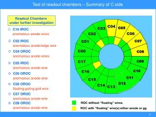
HCAL GranularitySummary • All readout towers in HB and HE participate in TPG sums • HO is NOT in trigger • HF is under negotiation and study • Some overlap in tower 16 have 5 readout channels in single TPG sum • Receiver card will handle it inside FPGA • We will probably have 2 FPGA/card • Means no more than 16 readout channels/TPG sum
1 2 3 4 5 6 7 8 9 10 11 12 13 14 15 16 HCAL GranularityHE Details • HE – entire wedge will be in TPG • 16 towers in h • Towers 1-13 have 2 readout depths • Both depths will contribute to TPG • Tower 14 has 2 readout depths • Last depth has RBX cutout • Both will contribute to TPG • Tower 15-16 has 3 readout depts • Last due to lack of HO • All 3 will contribute to TPG • Some HE towers will be added
16 17 18 19 20 21 22 23 24 25 26 27 28 HCAL Granularity • HE – entire wedge will be in TPG • 13 towers in h • Tower 16 has 2 readout depths • To be added to HB tower 16 TPG • Makes 5 total for that TPG tower • Towers 17-22 have 2 readout depths • Towers 23-18 have 4 readout depths • For radiation damage purposes
Simulation • Nominal HCAL pulse • Front-end electronics respose • QIE output per 25ns “bin” • Energy should be associated with bin 0
Pileup Studies(preliminary) • Start with p’s with ET=30 GeV in single tower h=0.4, f = p/2 Consistent with HCAL dominating resolution
Pileup Studies(preliminary) • Form Trigger towers (TPG) • Try ECAL algorithm with HCAL weights • Add energy in buckets [-4,+3] inclusive • Weights: [-.21, -.21, -.21, -.14, +.94, +.20, -.17, -.21] • Determined using ECAL method • Simpler method also being considered gives same answer • Use [-3,+1] weights [-1.5,-1.5,+1.0,+1.0,+1.0] • Under longer term study, is being pushed on • TPG from HCAL+ECAL • Increase in resolution from 5.4 to 5.6 GeV • Shift in ET by about 2 GeV
Pileup Studies(preliminary) • Contribution to TPG from HCAL alone • 100 MeV threshold kills lots of small ECAL TPGs…. 100 MeV TPG threshold After TPG quantization (units of 1 GeV) Some ECAL All HCAL ET
HCAL TPG ET “real” (from GEANT) Simulation (cont) • TPG vs “REAL” • Correction is ~15% over decent ET range
L1 Latency Estimates • HCAL TPG will use 5 trigger towers in the Level 1 Filter • HCAL will follow ECAL as much as possible • Same TTC distribution system • 6 TTCvi/TTCex, optical splitting, etc. • LVDS fanout to receiver cards and DCC • Use sync ASIC (or PLD) for TPG synch • Have not yet begun simulation of FPGA logic • Overall guess…. • ….same requirements as ECAL • ….fewer towers in sum • ….simpler weighting • ….we will be ok if ECAL is ok!