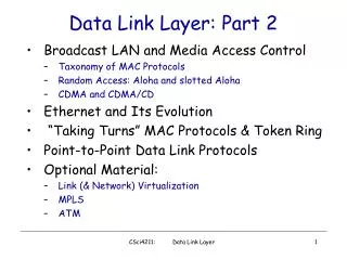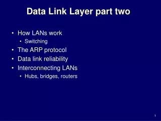
Data Link Layer part two
Data Link Layer part two. How LANs work Switching The ARP protocol Data link reliability Interconnecting LANs Hubs, bridges, routers. LAN technologies. LAN Addresses and ARP - 1. 32-bit IP address: network-layer address used to get datagram to destination network

Data Link Layer part two
E N D
Presentation Transcript
Data Link Layer part two • How LANs work • Switching • The ARP protocol • Data link reliability • Interconnecting LANs • Hubs, bridges, routers
LAN Addresses and ARP - 1 32-bit IP address: • network-layer address • used to get datagram to destination network • E.g. 138.23.169.129 LAN (or MAC or physical) address: • used to get datagram from one interface to another physically-connected interface (same network) • 48 bit MAC address (for most LANs) burned in the adapter ROM • E.g. 20:30:65:25:5a:93
LAN Addresses and ARP - 2 Each adapter on LAN has unique LAN address
LAN Address (more) • MAC address allocation administered by IEEE • manufacturer buys portion of MAC address space (to assure uniqueness) • Analogy: (a) MAC address: like Social Security Number (b) IP address: like postal address • MAC flat address => portability • can move LAN card from one LAN to another • IP hierarchical address NOT portable • depends on network to which one attaches
IP vs MAC address • IP address refers to communicating end points • used in network layer to find path • MAC or physical address refers to physically connected machines • Data link layer to find next hop
223.1.1.1 223.1.2.1 E B A 223.1.1.2 223.1.2.9 223.1.1.4 223.1.2.2 223.1.3.27 223.1.1.3 223.1.3.2 223.1.3.1 Data Link and Routing Starting at A, given IP datagram addressed to B: • look up net. address of B, find B on same net. as A • link layer send datagram to B inside link-layer frame frame source, dest address datagram source, dest address A’s IP addr B’s IP addr B’s MAC addr A’s MAC addr IP payload datagram frame
ARP: Address Resolution Protocol Question: how to determine MAC address of B given B’s IP address? • Each IP node (Host, Router) on LAN has ARPmodule, table • ARP Table: IP/MAC address mappings for some LAN nodes < IP address; MAC address; TTL> < ………………………….. > • TTL (Time To Live): time after which address mapping will be forgotten (typically 20 min)
ARP protocol: in one LAN • A knows B's IP address, wants to learn physical address of B • A broadcasts ARP query pkt, containing B's IP address • all machines on LAN receive ARP query • B receives ARP packet, replies to A with its (B's) physical layer address • A caches (saves) IP-to-physical address pairs until information becomes old (times out) • soft state: information that times out (goes away) unless refreshed
Routing to another LAN - 1 Walkthrough: routing from A to B via R
Routing to another LAN - 2 • A creates IP packet with source A, destination B • Routing: A finds that R is next hop • A uses ARP to get R’s physical layer address for 111.111.111.110 • A creates Ethernet frame with • R's physical address as dest, • A, B IP datagram • A’s data link layer sends Ethernet frame
Routing to another LAN - 3 • R’s data link layer receives Ethernet frame • R removes IP datagram from Ethernet frame, sees its destined to B • R uses ARP to get B’s physical layer address • R creates frame containing A-to-B IP datagram sends to B
Why retransmissions ? • Error correction although feasible, is not enough to handle all kinds of errors -- especially burst errors. • Corrupt frames cannot be deciphered and are therefore dropped. • Retransmissions needed to provide reliability. • Note this is reliability at the data link layer • Similar considerations appear at the transport layer • TCP has reliability
ACKs and Time-outs • When frames are sent piggyback an acknowledgement (ACK) for received packets onto sent packets. • If no ACK received up to a preset time-out, resend frame. • Called ARQ -- Automatic Repeat request. 1 Ack 1 100
Stop and Wait • Allow only one outstanding packet at any given time. • If ACK not received within time-out, send again.
How efficient is Stop and Wait? • Consider a 1.5 Mbps link with 45 ms RTT. • BW - Delay product = 67.5 Kb = 8KB. • You can fill 8 Kbytes of data prior to receiving an ACK. • However, if your frame size is 1 KB, you are using only 1/8 of the capacity. • Inefficient.
Sliding Window • What we really like is that the 9th frame be transmitted when ACK for the first frame arrives :). • Sliding window: • A window of packets sent • as ACKs are received window slides i.e., more packets sent. • Now what do we need in addition ? • Need to know which packets have been received and which have not. • Packets labeled using sequence numbers.
Some definitions • We have a window of packets sent -- Send Window Size or SWS. • Last Acknowledgement received is denoted LAR. • LFS represents the last frame sent. • NOTE: LFS - LAR <= SWS • NOTE 2: Initially we will consider “cumulative ACKs” • ACK frame seq-no=15 means I have received all packets including 15.
< SWS ─ ■ ■ ■ ■ ■ ■ LAR LFS Sender Functions k k+1 • When an ACK is received, the LAR moves to the right. • This allows for the transmission of an additional frames.
< ─ RWS ■ ■ ■ ■ ■ ■ LFR LAF Receiver functions Notation: RWS -- Receive Window Size LAF -- Largest Acceptable Frame. LFR -- Last Frame Received. • When frame with Seq_Num arrives: • If frame is outside window discard. • Seq_Num <= LFR or Seq Num > LAF • If frame within window, accept frame. • LFR < Seq_Num < LAF. • Send an ACK, if needed • Let Seq_Num_to_Ack be the largest seq-number • That I can ACK , (all frames <= Seq_Num_to_Ack have been received) • yet to be acked. • If have not sent ACK yet, send an ACK • Adjust parameters: • LFR = Seq_Num_to_Ack • Adjust LAF = LFR + RWS.
An Example • Let LFR =5 and RWS = 4. • This implies LAF = 9 • If packets 7 and 8 arrive (not 6), they are buffered. • Note that they are out of order. • Typically, Receiver will resend an ACK for packet 5. • When 6 arrives, it can cumulatively ACK all buffered packets i.e., it ACKs 8 and moves LFR to 8 and LAF to 12.
Other possibilities • Send NAK (negative acknowledgement) for lost packets -- example for 6, when 7 is received. • Duplicate ACKs -- send an ACK for 5 again when 7 is received to trigger retransmission of 6. • Selective ACKs : Explicitly ACK frames that are received -- more complex.
Setting the Window Size • Sender window: SWS, set considering the BW delay product and link quality • How many packets should be “on flight”? • Receiver window: RWS, set to something appropriate -- may depend on buffering resources. • If RWS = 1 what happens to out of order frames ?
Sequence number wrapping • Sequence numbers are finite -- thus there is a need to reuse -- called wrap around. • What is the relationship between the SWS and MaxSeqNum ?
Maximum Sequence Number and SWS • Should it not be SWS <= MaxSeqNum + 1 ? • Let us consider an example: • Sender has eight Seq Nums from 0 to 7. • Assume SWS = RWS = 7. • Sender transmits frames 0-6 • Receiver gets them, ACKs but ACKs get lost. • Receiver expects 7 and next 0...5. But sender sends the previous 0..5. • When the receiver gets these, he cannot distinguish. • Thus, when RWS = SWS, SWS < (MaxSeqNum+1)/2. • Example: consider MaxSeqNum = 1 (one bit) • I can only send one packet at a time, alternating between 1 and 0
Sequence Numbers and SWS • For other cases i.e., when RWS is not equal to SWS, other rules may apply. • Depends on the specific case. • A different way with TCP -- we will see later. • Easy solution -- large Sequence number space.
Interconnecting LANs • Hubs • Bridges • Routers
Interconnecting LANs Q: Why not just one big LAN? • Limited amount of supportable traffic: on single LAN, all stations must share bandwidth • Limited length: 802.3 specifies maximum cable length • Large “collision domain” (can collide with many stations) • Limited number of stations: 802.5 have token passing delays at each station
Overview: Order of increasing “intelligence’ • Hubs: • repeat everything to all ports except the incoming • only on tree topologies (otherwise -> loops) • Bridges: even with non-tree topologies • Select a tree structure and use only that • Default: behave like a hub • Learn: if known, forward only towards destination • Routers: • Handle arbitrary topologies • Perform complex routing decisions
Hubs - 1 • Physical Layer devices: essentially repeaters operating at bit levels: repeat received bits on one interface to all other interfaces • Each connected LAN referred to as LAN segment • Hubs do not isolate collisiondomains: node may collide with any node residing at any segment in LAN
Hub Advantages • simple, inexpensive device • Multi-tier provides graceful degradation: portions of the LAN continue to operate if one hub malfunctions • extends maximum distance between node pairs (100m per Hub)
Hub limitations • Single collision domain results in no increase in max throughput • multi-tier throughput same as single segment throughput • Individual LAN restrictions pose limits on number of nodes in same collision domain and on total allowed geographical coverage • Cannot connect different Ethernet types (e.g., 10BaseT and 100baseT)
Bridges - 1 • Link Layer devices: operate on Ethernet frames, examining frame header and selectively forwarding frame based on its destination • Bridge isolates collision domains since it buffers frames • When frame is to be forwarded on segment, bridge uses CSMA/CD to access segment and transmit
Bridges - 2 • Bridge advantages: • Isolates collision domains resulting in higher total max throughput, and does not limit the number of nodes nor geographical coverage • Can connect different type Ethernet since it is a store and forward device • Transparent: no need for any change to hosts LAN adapters
Bridges: frame filtering, forwarding • Bridges filter packets • Same-LAN -segment frames not forwarded onto other LAN segments • Forwarding: • How to know which LAN segment on which to forward frame? • Looks like a routing problem (more shortly!)
Bridge Filtering - 1 • Bridges learn which hosts can be reached through which interfaces: maintain filtering tables • when frame received, bridge “learns” location of sender: incoming LAN segment • records sender location in filtering table • Filtering table entry: • (Node LAN Address, Bridge Interface, Time Stamp) • stale entries in Filtering Table dropped (TTL can be 60 minutes)
Bridge Filtering - 2 • Filtering procedure: if destination is on LAN on which frame was received then drop the frame else { lookup filtering table if entry found for destination then forward the frame on interface indicated; else flood; /* forward on all but the interface on which the frame arrived*/ }
Bridge Learning: example - 1 Suppose C sends frame to D and D replies back with frame to C • C sends frame, bridge has no info about D, so floods to both LANs • bridge notes that C is on port 1 • frame ignored on upper LAN • frame received by D
Bridge Learning: example - 2 C | 1 • D generates reply to C, sends • bridge sees frame from D • bridge notes that D is on interface 2 • bridge knows C on interface 1, so selectively forwards frame out via interface 1
Disabled Bridges Spanning Tree • For increased reliability, desirable to have redundant, alternate paths from source to dest • With multiple simultaneous paths, cycles result - bridges may multiply and forward frame forever • Solution: organize bridges in a spanning tree by disabling subset of interfaces
The Spanning Tree Algorithm • Purpose: select a subset of ports for fwd-ing • Root bridge election: lowest ID wins • Each bridge: select one port towards root • Shortest path to root (break ties) • In each LAN: select designated bridge - select port • Root is designated for all adjacent LANs • Designated bridge: fwds frames towards root • Select the bridge closest to root (IDs to break ties) • Note: a bridge can be designated for many LANs • Active ports: the selected ones, others are stand by PetDavie 3.2.2 for more details
WWF Bridges vs. Routers • Both store-and-forward devices • routers: network layer devices (examine network layer headers) • bridges are Link Layer devices • Routers maintain routing tables, implement routing algorithms • Bridges maintain filtering tables, implement filtering, learning and spanning tree algorithms
Routers vs. Bridges - 1 Bridges + and - + Bridge operation is simpler requiring less processing bandwidth - Topologies are restricted with bridges: a spanning tree must be built to avoid cycles - Bridges do not offer protection from broadcast storms (endless broadcasting by a host will be forwarded by a bridge)
Routers vs. Bridges - 2 Routers + and - + arbitrary topologies can be supported, cycling is limited by TTL counters (and good routing protocols) + provide firewall protection against broadcast storms - require IP address configuration (not plug and play) - require higher processing bandwidth • Bridges do well in small (few hundred hosts) while routers used in large networks (thousands of hosts)