Part III. Data Link Layer
Part III. Data Link Layer. Chapters 13. Wired LANs Chapter 15. Wireless LANs Chapter 17. Connecting LANs,. COMP 3270 Computer Networks Computing Science Thompson Rivers University. Course Outline. Overview Physical Layer Digital transmission Analog transmission Bandwidth utilization

Part III. Data Link Layer
E N D
Presentation Transcript
Part III. Data Link Layer Chapters 13. Wired LANs Chapter 15. Wireless LANs Chapter 17. Connecting LANs, ... COMP 3270 Computer Networks Computing Science Thompson Rivers University
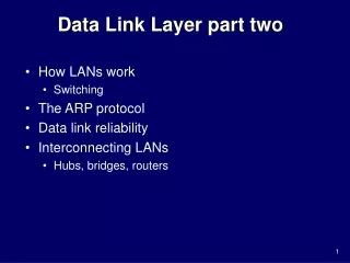
Course Outline • Overview • Physical Layer • Digital transmission • Analog transmission • Bandwidth utilization • … • Data Link Layer • Error detection • Data link control • Multiple access • Ethernet; Wireless LANs; Connecting LANs • Network Layer • Logical addressing • IPv4, protocols • Delivery, forwarding and routing
Learning Objectives • Understand the architecture of WLAN. • Understand the architecture of Bluetooth. • Match major layers with hub, bridge, switch, router and gateway. • List advantages of using VLANs.
13.1 IEEE STANDARDS In 1985, the Computer Society of the IEEE started a project, called Project 802, to set standards to enable intercommunication among equipments from a variety of manufacturers. Project 802 is a way of specifying functions of the physical layer and the data link layer of major LAN protocols.
13.2 STANDARD ETHERNET The original Ethernet was created in 1976 at Xerox’s Palo Alto Research Center (PARC). Since then, it has gone through four generations. We briefly discuss the Standard (or traditional) Ethernet in this section.
802.3 MAC frame Post- amble Length or protocol ID Data length: < 1518 = (0x600) Protocol ID: >= 1536 CRC-32 IEEE 802.3 Ethernet II
Minimum and maximum lengths ☺ What if an IP packet of 40 bytes is stored?
15.2 IEEE 802.11 IEEE has defined the specifications for a wireless LAN, called IEEE 802.11, which covers the physical and data link layers.
A BSS without an AP is called an ad hoc network; a BSS with an AP is called aninfrastructure network.
Physical layers PSK or QAM 802.11n – 802.11g with MIMO (multiple input multiple output) antennas
15.3 BLUTOOTH Bluetooth is a wireless LAN technology designed to connect devices of different functions such as cellphones, tablet computers, notebooks, computers, cameras, printers, coffee makers, and so on. A Bluetooth LAN is an ad hoc network, which means that the network is formed spontaneously.
Master/slave (maximum 8 stations) 2.4 GHz ISM band 1Mbps; 3Mbps in the 2nd generation TDMA
17.1 CONNECTING DEVICES In this section, we divide connecting devices into five different categories based on the layer in which they operate in a network. Topics discussed in this section: • Passive Hubs • Active Hubs • Bridges • Two-Layer Switches • Routers • Three-Layer Switches • Gateways
A repeater forwards every frame; it has no filtering capability.
A hierarchy of hubs ☺ Collision domain is ??? Multi-port repeater
Bridges A bridge has a table used in filtering decisions.
It needs to read the addresses => data link layer ☺ Collision domain is ??? Information can be learned.
Collision domains in an unbridged network and a bridged network
Switches (L2 Switches) ☺ Could there be packet collisions? No.
Routers (L3 Switches) Routers connecting independent LANs and WANs
17.2 BACKBONE NETWORKS A backbone network allows several LANs to be connected. In a backbone network, no station is directly connected to the backbone; the stations are part of a LAN, and the backbone connects the LANs. Topics discussed in this section: • Bus Backbone • Star Backbone • Connecting Remote LANs
Bus Backbone Old days
Star Backbone These days
17.3 VIRTUAL LANs We can roughly define a virtual local area network (VLAN) as a local area network configured by software, not by physical wiring. Topics discussed in this section: • Membership • Configuration • Communication between Switches • IEEE Standard • Advantages
A switch connecting three LANs A ☺ The project in which A has been involved is now completed, and so A needs to move to another project group, e.g., Group 2. Then does A need to move to another office? Is there any other easier way to reconfigure logical groups of computers without moving?
A switch using VLAN software VLAN (Virtual LAN) : a local area network configured by software, not by physical wiring => flexible reconfiguration (broadcasting possible)
Two switches in a backbone using VLAN software IEEE 802.1Q Over a trunk
IEEE 802.1Q IEEE 802.1Q Over a trunk Router; Firewall This system has to know about VLANs.
Logically Router; Firewall LAN3 LAN1 LAN2
☺ Advantages ? o Easy change/creation of broadcast domains => Flexible reconfiguration; Some software requires broadcast, e.g., Novel NetWare to share printers and files; o Easy change/creation of IP logical networks; o Easy implementation of firewall at a central router; o Less networking devices at a central router;