Part III : Data Link Layer Error Detection and Correction
Chapter 10. Part III : Data Link Layer Error Detection and Correction. Error Detection and Correction. What does accuracy means? What about corrupted message ? Which layer is responsible for error detection and correction? Does all application has the same sensitivity to errors?.

Part III : Data Link Layer Error Detection and Correction
E N D
Presentation Transcript
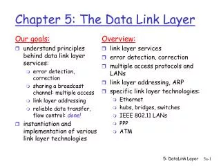
Chapter 10 Part III: Data Link LayerError Detection and Correction
Error Detection and Correction What does accuracy means? What about corruptedmessage? Which layer is responsible for error detection and correction? Does all application has the same sensitivity to errors? Data can be corrupted during transmission. Some applications require that errors be detected and corrected. 10.2
Error Detection and Correction By the End of this Chapter you will be able to: Understand different Types of Errors & Redundancy Detection Versus Correction Forward Error Correction Versus Retransmission Coding 10.4 CYCLIC CODES CRC Cyclic Redundancy Check Polynomials Cyclic Code Analysis Advantages of Cyclic Codes Other Cyclic Codes 10.5 CHECKSUM Idea /One's Complement /Internet Checksum 10.3
10-1 INTRODUCTION Let us first discuss some issues related, directly or indirectly, to error detection and correction. 10.5
10.1.1 Types of Errors • Whenever bits flow from one point to another, they are subject to unpredictable changes because of interference. • There are two types of errors: • Single-Bit Error means that only 1 bit of a given data unit is changed from 1 to 0 or from 0 to 1. • Burst Error means that 2 or more bits in the data unit have changed from 1 to 0 or from 0 to 1. 10.6
Figure 10.1: Single-bit and burst error NOTE: Burst error is more likely to occur than a single-bit error 10.7
10.1.2 Redundancy The central concept in detecting or correcting errors is redundancy. To be able to detect or correct errors, we need to send some extra bits with our data. These redundant bits are added by the sender and removed by the receiver. Their presence allows the receiver to detect or correct corrupted bits. 10.8
10.1.3 Detection versus Correction The correction of errors is more difficult than the detection. WHY? In error correction, we need to know the exact number of bits that are corrupted and, more importantly, their location in the message. However, in error detection we need only to know is there an error or not. 10.9
10.1.4 Coding • Redundancy is achieved through various coding schemes. • The sender adds redundant bits through a process that creates a relationship between the redundant bits and the actual data bits. • The receiver checks the relationships between the two sets of bits to detect errors. • The ratio of redundant bits to data bits and the robustness of the process are important factors in any coding scheme. 10.10
10.1.4 Coding • We can divide coding schemes into two broad categories: • Block coding • Convolution coding 10.11
10.1.5 Modulo Arithmetic In modulo-N arithmetic, we use only the integers in the range 0 to N - 1, inclusive. Example: clock system (12 numbers but we use 0 to 11) Modulo-2 Arithmetic 0+0=0 0+1=1 1+0=1 1+1=0 0-0=0 0-1=1 1-0=1 1-1=0 addition and subtraction give the same results. In this arithmetic we use the XOR (exclusive OR) operation for both addition and subtraction 10.12
10-2 BLOCK CODING • In block coding, we divide our message into blocks, each of k bits, called datawords. • We add r redundant bits to each block to make the length n = k + r. The resulting n-bit blocks are called codewords. • How the extra r bits are chosen or calculated is something we will discuss later. 10.13
10.2.1 Error Detection How can errors be detected by using block coding? If the following two conditions are met, the receiver can detect a change in the original codeword. 1. The receiver has (or can find) a list of valid codewords. 2. The original codeword has changed to an invalid one. 10.14
Figure 10.6: Process of error detection in block coding 10.15 10.15
Example 10.2 Let us assume that k = 2 and n = 3. Table 10.1 shows the list of datawords and codewords. Later, we will see how to derive a codeword from a dataword. Table 10.1: A code for error detection in Example 10.1 10.16
Error Detection Methods 10.17
1. Parity Check • The most common and least expensive. • Simple or Two Dimensional. How does it work? A k-bit dataword is changed to an n-bit codeword where n = k + 1. The extra bit,called the paritybit, is selected to make the total number of 1s in the codewordeven. Example: Assume the sender sends the dataword1011. Since the number of 1's is odd then the parity bit is equal to 1 and the codewordfor this datawordis 10111. 10.18
Parity Check NOTE: Simple parity check can detect all single-bit errors. It can detect burst errors only if the total number of errors in each data unit is odd. A betterapproach is the two-dimensional paritycheck which organizes the data units into table (rows and columns). The parity bit for each column is Calculated and added to the table as a new row (column parity) 10.19
1.2 Two-dimensional parity Calculate the parity bit for each data unit, then organize them into table (rows and columns) Calculate the parity bit for each column and create a new row (column parity) A redundant row of bits is added to the whole block.
Note In two-dimensional parity check, a block of bits is divided into rows and a redundant row of bits is added to the whole block.
Example Suppose the following block is sent: 10101001 00111001 11011101 11100111 10101010 However, it is hit by a burst noise of length 8, and some bits are corrupted. 10100011 10001001 11011101 11100111 10101010 When the receiver checks the parity bits, some of the bits do not follow the even-parity rule and the whole block is discarded.( see next slide)
Two-dimensional Performance Increases the likelihood of detecting burst errors. A redundancy of n-bits can detect a burst error of n bits. A burst error of more than n bits is also detected with a very high probability. One pattern of errors still elusive: If 2 bits in one data unit are damaged and two bits in exactly the same position in anther data unite are also damaged. The error will not be detected.
10.4.1. Cyclic Redundancy Check In this section, we simply discuss a subset of cyclic codes called the cyclic redundancy check (CRC), which is used in networks such as LANs and WANs. In a cyclic code, if a codeword is cyclically shifted (rotated), the result is another codeword. Example: if 1011000 is a codeword and we cyclically left-shift, then 0110001 is also a codeword. 1 10.26
The Process of CRC At the Sender: the encoder, the dataword has k bits(4 here).The codeword has n bits( 7). The size of the dataword is augmented by addingn-k (3 here) 0s to the right-hand size of the word. The generator uses a divisor of size n-k-1 (4 here), predefined and agreed upon. The generator divides the augmented dataword by the divisor ( modulo-2 division). The reminder is appended to the dataword to create the codeword. 10.29
The Process of CRC • At the Receiver: • The decoder does the same division process as the encoder. • The reminder of the division is the syndrome. • If the syndrome is all 0s, there is no error, the dataword separated from the received codeword and accepted. • Otherwise, everything is discarded. 10.30
Figure 10.16: Division in the CRC decoder for two cases 10.32
10.4.2 Polynomials • A better way to understand cyclic codes and how they can be analyzed is to represent them as polynomials. • A pattern of 0s and 1s can be represented as a polynomial with coefficients of 0 and 1. • The power of each term shows the position of the bit; the coefficient shows the value of the bit. 10.33
Figure 10.21: A polynomial to represent a binary word Note that: the degree of a polynomial is 1 less that the number of bits in the pattern. What is the polynomial degree and bit pattern for x6+ x+ 1? 10.34
Hardware Implementation for a Divisor in CRC Although CRC division may be performed in software, it is usually performed using a feedbackshift register and XOR gates. Let us take the following polynomial as the divisorx6+ x+ 1 Input Data ( dataword / Rc codeword ) + + X1 X0 X6 + The feedback taps are determind by the coefficent of the generated polynomial. The divisor line and XOR are missing if the corresponding bit in the divisor is O. No lines for X2, X3, X4 and X5 10.35
Polynomial Arithmetic for CRC Adding and Subtracting Polynomials x5+ x4+ x2 x5+ x4+ x2 x6+ x4+ x2 x6+ x4+ x2 + x5+ x2+ x1 + x6+ x5 x6+ x2+ x1 Multiplying or Dividing Terms It is the same as the binary division. Shifting Shifting left 3 bits (multiplying by x3): 10011 becomes 10011000 or x4+ x +1 becomesx7+ x4+x3 Shifting right 3 bits (dividing by x3): 10011 becomes 10 or x4+ x +1 becomes x 10.36
10.4.3 Encoder Using Polynomials Now that we have discussed operations on polynomials, we show the creation of a codeword from a dataword. Figure 10.9 is the polynomial version of Figure 10.6. We can see that the process is shorter. 10.37
10.4.4 Cyclic Code Analysis The divisor in a cyclic code is normally called the generator polynomial or simply the generator. We can analyze a cyclic code to find its capabilities by using polynomials. We define the following, where f(x) is a polynomial with binary coefficients. 10.39
Example 10.15 Which of the following g(x) values guarantees that a single-bit error is caught? x + 1, x3 and 1 Solution 10.40
Figure 10.23: Representation of isolated single-bit errors 10.41
Example 10.16 Find the suitability of the following generators in relation to burst errors of different lengths: x6 + 1, x18 + x7 + x + 1, and x32 + x23 + x7 + 10. Solution 10.42
10.4.5 Advantages of Cyclic Codes • Cyclic codes have a very good performance in detecting single-bit errors, double errors, an odd number of errors, and burst errors. • In burst error CRC can detect all burst errors that affect an odd number of bits, errors of length less than or equal to the degree of the polynomial, and it can detect, with very high probability, burst errors of length greater than the degree of the polynomial. • They can easily be implemented in hardware and software. They are especially fast when implemented in hardware. This has made cyclic codes a good candidate for many networks. 10.44
Example The CRC-12 x12 + x11 + x3 + x + 1 which has a degree of 12, will detect: 1. all burst errors affecting an odd number of bits, 2. will detect all burst errors with a length less than or equal to 12, and 3. will detect, 99.97 percent of the time, burst errors with a length of 12 or more. 10.45
10-5 CHECKSUM • Checksum is an error-detecting technique that can be applied to a message of any length. • In the Internet, the checksum technique is mostly used at the network and transport layer rather than the data-link layer. • Like CRC, checksum based on the concept of redundancy. 10.46
Figure 10.15: Checksum 10.47
Checksum Concept 10.48
Example 10.18 Suppose the message is a list of five 4-bit numbers that we want to send to a destination. In addition to sending these numbers, we send the sum of the numbers. For example, if the set of numbers is (7, 11, 12, 0, 6), we send (7, 11, 12, 0, 6, 36), where 36 is the sum of the original numbers. The receiver adds the five numbers and compares the result with the sum. If the two are the same, the receiver assumes no error, accepts the five numbers, and discards the sum. Otherwise, there is an error somewhere and the message not accepted. 10.49
Example 10.20 In the previous example, the decimal number 36 in binary is (100100)2. To change it to a 4-bit number we add the extra leftmost bit to the right four bits as shown below. Instead of sending 36 as the sum, we can send 6 as the sum (7, 11, 12, 0, 6, 6). The receiver can add the first five numbers in one’s complement arithmetic. If the result is 6, the numbers are accepted; otherwise, they are rejected. 10.50