Download
1 / 42
420 likes | 598 Vues
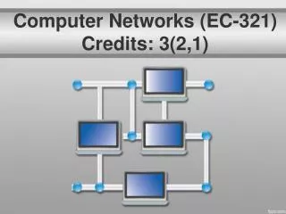
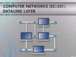
Computer Networks (EC-321) DataLink Layer. Outline. Design Issues Error Detection and Correction Elementary Data Link Protocols Sliding Window Protocols Protocol Specification and Verification Example Data Link Protocols. Data Link Layer.

E N D
Outline • Design Issues • Error Detection and Correction • Elementary Data Link Protocols • Sliding Window Protocols • Protocol Specification and Verification • Example Data Link Protocols
Data Link Layer • In general, the functions of the data link layer include: • Providing a well-defined service interface to the network layer (framing) • Dealing with transmission errors (error control) • Regulating the flow of data so that slow receivers are not swamped by fast senders (flow control) • To accomplish these goals, packets from the network layers are encapsulated into frames:
Data Link Layer • Services provided to the network layer: • unacknowledged connectionless service • No ACKs and hence no retransmissions (at the data link level). Appropriate for low-error rate environments and real-time traffic (e.g., digitized voice). Used in many LANs. • acknowledged connectionless service • Each frame individually acknowledged. Retransmissions occur for negative ACKs (NACKs) or missing ACKs (timeout by sender). • acknowledged connection-oriented service • Connection established before frames sent. Frames contain sequence numbers. Guarantees that each frame is passed to network layer exactly once at receiving side. • The actual services that are offered vary from protocol to protocol.
Functions of Data Link Layer • To accomplish the general functions of handling errors and regulating data flow, there are three specific things the DLL does. • Framing • partition stream into units called frames • perform error detection/correction on frames • retransmission on frame basis • Error Control • both detection and correction schemes may be used • what is done in response to detection depends on protocol • Flow Control • prevents sender from “swamping” the receiver • normally built into the protocol
Framing • Deciding, at the receiving end, where frames start and stop and filling idle periods • Four types of framing are used • byte count • frame length given in header field • character-based framing: • special characters (flag bytes) used with byte stuffing • bit-oriented framing: • special bit sequences (flag bits) used with bit stuffing • violations of physical layer encoding • Ex. high-high or low-low in Manchester encoding • No character- or bit-stuffing is required
Length Count • Header contains length of frame • Problems • count may become corrupted • receiver has no way to tell where next frame starts • Rarely used alone, often used in conjunction with another framing method, as a double-check • Example:
Character OrientedFraming • special characters • DLE STX - start of text • DLE ETX - end of text • SYN - synchronous idle, between frames • Ex. IBM BISYNC • character stuffing • required if delimiters appear in data • soln: insert extra DLE before each DLE in data • extra “stuffed” DLE’s extracted at receiving end
Bit OrientedFraming • Disadvantage of character-oriented framing: • Start- and stop-frame pattern: 0 1 1 1 1 1 1 0 • Bit stuffing • sender stuffs 0 after every sequence of five 1’s • when receiver sees five 1’s followed by 0, extracts the 0 • boundary between two frames can be unambiguously recognized • Example: • 1 1 1 1 1 1 0 1 1 1 1 1 1 1 1 1 1 1 0 1 1 1 1 1 0 • Why do we have to stuff after five 1’s, even if followed by a 0?
ERROR DETECTION AND CORRECTION • Channels, especially wireless links and aging local loops, have error rates that are orders of magnitude larger. • Two basic strategies for dealing with errors • error-correcting codes (ECC) • include enough redundant information to enable the receiver to deduce what the transmitted data must have been. • not as widely used in communications as error detection • ex. Hamming code • error-detecting codes (EDC) • include only enough redundancy to allow the receiver to deduce that an error has occurred (but not which error). • frame is retransmitted • ex. parity checks, cyclic redundancy codes • Neither ECC nor EDC can handle all possible errors since the redundant bits that offer protection are as likely to be received in error as the data bits (which can compromise their protection)
ERROR CORRECTING • Frame consists of m data bits, r check bits. n = m + r. An n-bit unit is referred to as a codewordand an (n,m) referred to as code. • code rate = m/n (might be ½ or close to 1, reason?) • Block code • the r check bits are computed solely as a function of the m data bits with which they are associated • Linear code • the r check bits are computed as a linear function of the m data bits • Systematic code, • the m data bits are sent directly, along with the check bits, rather than being encoded themselves before they are sent (doubt)
ERROR CORRECTING • Four different error-correcting codes: • Hamming codes. • Binary convolutional codes. • Reed-Solomon codes. • Low-Density Parity Check codes. • Error correcting codes seldom used in communications, except space. • To determine how many bits differ, just XOR the two codewords and count the number of 1 bits in the result. • The number of bits by which two codewords differ is called the Hamming distance. • The minimum distance found (by comparing all pairs of codewords) is the Hamming distance of the code.
ERROR CORRECTING • To detect d-bit errors, need (code) distance of b = d+1. Ex. codewords with single parity bit have distance of 2. • To correct d-bit errors, need (code) distance of b = 2d+1. We correct to closest codeword. • Example 0000000000, 0000011111, 1111100000, and 1111111111 • This code has a distance of 5, which means that it can correct double errors or detect quadruple errors. If the codeword 0000000111 arrives and we expect only single- or double-bit errors, the receiver will know that the original must have been 0000011111. If, however, a triple error changes 0000000000 into 0000000111, the error will not be corrected properly.
Hamming Code • Features and technique (a more general one): • it is a block code, meaning that it divides a bit stream into fixed-length blocks. • the bits are numbered 1 to n • bits numbered as powers of 2 are check bits • the value of each check bit 2k depends on the parity of the bits whose label contains that 2kwhen written as the sum of powers of 2 • to find incorrect bit, determine if check bits are correct, adding 2kto a counter if check bit 2kis of the wrong parity • The sum of the incorrect check bits is called the error syndrome, which identifies the incorrect bit
Hamming Code (Example) • (11,7) Hamming code with 7 data bits (m) and 4 check bits (r) • Data bits = 1000001 • n = m + r = 7 + 4 = 11 • write each bit position, 1 through 11, in powers of 2 1 = 20 5 = 22+ 20 9 = 23+ 20 2 = 21 6 = 22+ 21 10 = 23+ 21 3 = 21+ 207 = 22+ 21+ 20 11 = 23+ 21+ 20 4 = 22 8 = 23 • bits numbered as powers of 2 are check bits _ _ 1 _ 0 0 0 _ 0 0 1
Hamming Code (Example) • bits numbered as powers of 2 are check bits _ _ 1 _ 0 0 0 _ 0 0 1
Hamming Code (Example) • Decoding 0 0 1 0 1 0 0 1 0 0 1 (Received codeword) 4 + 1 = 5 (bit is in error, flip it )
Convolution Codes • An encoder processes a sequence of input bits and generates a sequence of output bits. • There is no natural message size or encoding boundary as in a block code. • The output depends on the current and previous input bits (memory) • Convolutional codes are widely used in deployed networks, for example • part of the GSM mobile phone system • satellite communications • 802.11
Convolution Codes • Code rate: ratio of input bits to output bits • Constraint length: number of prior bits on which an output depends • Example: • Code rate r = 1/2 • Constraint length k = 7
Convolution Codes • The internal state is kept in six memory registers. • Each time another bit is input the values in the registers are shifted to the right. • For example • Input is 111 • Initial state all zeros • the internal state, written left to right, will become 100000, 110000, and 111000 after the first, second, and third bits have been input. • The output bits will be 11, followed by 10, and then 01. • It takes seven shifts to flush an input completely so that it does not affect the output. • The constraint length of this code is thus k = 7.
Convolution Codes Decoding • Maximum Likelihood • Finding the sequence of input bits that is most likely to have produced the observed sequence of output bits (which includes any errors). • For small values of k, this is done with a widely used algorithm developed by Viterbi
Reed-Solomoncode • While Hamming codes operate on individual bits, Reed-Solomon codes operate on m-bit symbols. • Reed-Solomon code features • defined as polynomials operating over finite fields • for an m-bit symbol, codewords are 2m − 1 symbols long • strong error correction properties, especially for burst errors • Decoding with error correction is done with an algorithm developed by Berlekamp and Massey • Application • DSL , data over cable, satellite communications, and perhaps most ubiquitously on CDs, DVDs, and Blu-ray discs
LDPC (Low-DensityParity Check) code • Low-Density Parity Check (LDPC) codes: • Linear block codes • Output bits are formed from a small fraction of input bits, represented by a matrix with a low density of 1s • Received codewords are decoded with an approximation algorithm • Outperform most other codes. Included in 10 Gbps Ethernet and latest 802.11
Error Detection • Error detection and retransmission is usually more efficient for dealing with the occasional error. • Three different error-detecting codes. They are all linear, systematic block codes: • 1. Parity. • 2. Checksums. • 3. Cyclic Redundancy Checks (CRCs).
Parity • Single parity bit is appended to the data. • The parity bit is chosen so that the number of 1 bits in the codeword is even (or odd). • For example: • Even Parity : a bit is added to the end of data , 1011010, to make it 10110100. • Odd Parity: 1011010 becomes10110101 • To merely detect a block with a single 1-bit error, one parity bit per block will suffice (e.g hamming required more bits).
Parity • Problem: • single parity bit can only reliably detect a single-bit error in the block • If block is badly garbled by a long burst error, the probability that the error will be detected is only 0.5, which is hardly acceptable. • Improvement: • block = rectangular (k , n) bits matrix • send one parity bit for each row • up to k bit errors will be reliably detected as long as there is at most one error per row • Interleaving • More better protection against burst errors • compute the parity bits over the data in a different order than the order in which the data bits are transmitted
Parity (Interleaving) • Compute a parity bit for each of the n columns. • Send all the data bits as k rows. • At the last row, we send the n parity bits • Example: • for n = 7 and k = 7 • This method uses n parity bits on blocks of kndata bits to detect a single burst error of length n or less • A burst of length n + 1 will pass undetected • A burst error, just implies that at least the first and last bits are wrong
Checksum • ‘‘checksum’’ is often used to mean a group of check bits associated with a message, regardless of how are calculated. • A group of parity bits is one example of a checksum. • Stronger checksums based on a running sum of the data bits of the message. • Placed at the end of the message, as the complement of the sum function. • errors may be detected by summing the entire received codeword, both data bits and checksum. If the result comes out to be zero, no error has been detected.
Checksum • Example: Suppose the following block of 16 bits is to be sent using a checksum of 8 bits. 10101001 00111001 The numbers are added 10101001 00111001 ------------- Sum 11100010 Checksum 00011101 ; complemented The pattern sent is 10101001 00111001 00011101
Checksum • Example: Now suppose the receiver receives the pattern sent in is 10101001 00111001 00011101 When the receiver adds the three sections, it will get all 1s, which, after complementing, is all 0s and shows that there is no error. 10101001 00111001 00011101 Sum 11111111 Complement 00000000 Means that the pattern is OK.
Checksum • Example: Calculating a checksum (IP packet) • The header is shown in bold and the checksum is underlined. 4500 0073 0000 4000 4011 b861 c0a8 0001c0a8 00c7 0035 e97c 005f 279f 1e4b 8180 • 4500 + 0073 + 0000 + 4000 + 4011 + c0a8 + 0001 + c0a8 + 00c7 = 2479C (equivalent to 149,404 in decimal) • 2479C to binary: 0010 0100 0111 1001 1100 • The first nibble (4 bits) are the carry and will be added to the rest of the value: 0010 + 0100 0111 1001 1100 = 0100 0111 1001 1110 • Next, we flip every bit (1’s compliment) in that value, to obtain the checksum: 1011 1000 0110 0001This is equal to B861 in hexadecimal, as shown underlined in the original IP packet header.
Checksum • Example: Verifying a checksum (IP Packet) • When verifying a checksum, the same procedure is used as above, except that the original header checksum is not omitted.4500 + 0073 + 0000 + 4000 + 4011 + b861 + c0a8 + 0001 + c0a8 + 00c7 = 2fffd • Add the carry bits:fffd + 2 = ffff • Taking the ones' complement (flipping every bit) yields 0000, which indicates that no error is detected.
CRC • the CRC (Cyclic Redundancy Check), also known as a polynomial code • 110001 has 6 bits and thus represents a six-term polynomial with coefficients 1, 1, 0, 0, 0, and 1: 1x5+ 1x4+ 0x3+ 0x2+ 0x1+ 1x0. • the sender and receiver must agree upon a generator polynomial, G(x), in advance • Both the high- and low order bits of the generator must be 1 • the frame must be longer than the generator polynomial
CRC • The algorithm for computing the CRC is as follows: • 1. Let r be the degree of G(x). Append r zero bits to the low-order end of the frame so it now contains m + r bits and corresponds to the polynomial xrM(x). • 2. Divide the bit string corresponding to G(x) into the bit string corresponding to xrM(x), using modulo 2 division. • 3. Subtract the remainder (which is always r or fewer bits) from the bit string corresponding to x rM(x) using modulo 2 subtraction. The result is the checksummed frame to be transmitted. Call its polynomial T(x).
CRC • Example: • calculation for a frame 1101011111 using the generator G(x) = x4+ x + 1.
CRC sent: 110010100 = F(x) error: 000001000 = E(x) = x3 -------------- received: 110011100 = F(x) + E(x) (error in bit 3) • A single bit error in bit position K in a message F(x) can be represented by adding the term E(x) = xK, (binary 1 followed by K-zeros). • The above error would be detected when the CRC division is performed: 100101 (ignore this quotient) ---------------- 1101) 110011100 = F(x) + E(x) 1101 ---- 1111 1101 ---- 1000 1101 ---- 101 = remainder (error!)
CRC • D(x) ≡ data • G(x) ≡ generator polynomial • T(x) ≡ transmitted bits • R(x) ≡ received bits • E(x) ≡ error bits • Know: R(x) = T(x) +E(x) • Since E(x) = xK has no factors other than x, a single bit error will never produce a term exactly divisible by P(x). All single bit errors will be detected.
CRC • D(x) ≡ data • G(x) ≡ generator polynomial • T(x) ≡ transmitted bits • R(x) ≡ received bits • E(x) ≡ error bits • Know: R(x) = T(x) +E(x) • Since E(x) = xK has no factors other than x, a single bit error will never produce a term exactly divisible by P(x). All single bit errors will be detected.
CRC • CRC codes are the most common error detection scheme used in communications • Detection capabilities in detecting errors depends on G(x). • all single errors if G(x) contains two or more terms • all double errors if • x does not divide G(x), and • G(x) does not divide xk +1, for any k < K, where K is the frame length • all odd errors if G(x) contains x+1 as a factor • all burst errors of length r or less, where r is degree of G(x) • burst errors of length r +1 will be missed with probability 1/2r−1 • burst errors of length r +2 or more will be missed with probability 1/2r
CRC • Similarly if E(x) = xK + xK+1, the error pattern includes two adjacent bits (e.g. E(x) = 000011000 for K=3). • Since this E(x) has no factors other than (x+1) and x, a double bit error will never produce a term exactly divisible by P(x). All double bit (adjacent-bit) errors will be detected • The above argument can be extended to other types of errors, and the error performance can be fully described by examining E(x) independently of any data messages.
CRC • CRC-12 = x12 +x11 +x3 +x2 +x1 +1 • Has x+1 as prime factor. • Used when character length is 6 bits. Why? • CRC-16 = x16 +x15 +x2 +1 • CRC-CCITT = x16 +x12 +x5 +1 • Have x+1 as prime factor. • Used when character length is 8 bits. • Catch all single, double errors, odd errors. • Catch all burst errors of length 16 or less. • Catch 99.997% of burst errors of length 17. • Catch 99.998% of all burst errors of length 18 or more. • CRC-32 = x32+x26 +x23 +x22 +x16 +x12 +x11 +x10+x8 +x7 +x5 +x4 +x2 +x+1 • 99.99999997% of all burst errors of length 34 or more.