Download

1 / 38
380 likes | 508 Vues
This chapter explores the critical role of Input/Output (I/O) modules in computer architecture, detailing why peripherals cannot be directly connected to the system bus. It covers various types of I/O devices, including human-readable devices, machine-readable ones, and communication interfaces like modems. The chapter discusses different data transfer techniques, including programmed I/O, interrupt-driven I/O, and Direct Memory Access (DMA). Key concepts such as control and timing, device communication, and error detection are examined, illustrating how CPUs manage data transfer with peripherals efficiently.

E N D
Dr Mohamed MenacerCollege of Computer Science and EngineeringTaibah Universityeazmm@hotmail.comwww.mmenacer.info. Chapter 4: Input/Output CE-321: Computer Architecture William Stallings, Computer Organization and Architecture, 8th Edition
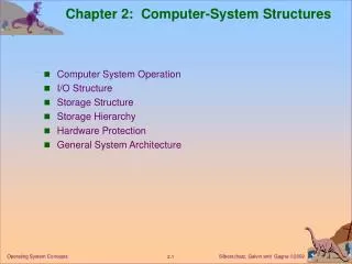
Why peripherals are not connected directly to the system bus • Wide variety of peripherals • Delivering different amounts of data • At different speeds • In different formats • Data transfer rate of peripherals often much slower than CPU and RAM • Some peripherals data transfer rate is faster than that of memory or processor. • Need I/O module
Input/Output Module • Interface to processor and memory via the system bus or central switch • Interface to one or more peripheral devices by data links.
External Devices • Human readable • Screen, printer, keyboard • Machine readable • Monitoring and control • Magnetic disk, tape systems, sensors and actuators such as used in robotics application. • Communication • Modem • Network Interface Card (NIC)
I/O Module Function • Control & Timing • CPU Communication • Device Communication • Data Buffering • Error Detection
I/O Steps: the control of the transfer of datafrom an external device to processor involve: • CPU checks I/O module device status • I/O module returns device status • If ready, CPU requests data transfer • I/O module gets data from device • I/O module transfers data to CPU • Variations for output, DMA, etc.
Input Output Techniques • Programmed • Interrupt driven • Direct Memory Access (DMA)
Programmed I/O • CPU has direct control over I/O • Sensing status • Read/write commands • Transferring data • CPU waits for I/O module to complete operation • Wastes CPU time
I/O Commands • CPU issues address • Identifies module (& device if >1 per module) • CPU issues command • Control - telling module what to do • e.g. spin up disk • Test - check status • e.g. power? Error? • Read/Write • Module transfers data via buffer from/to device
Addressing I/O Devices • Under programmed I/O data transfer is very like memory access (CPU viewpoint) • Each device given unique identifier • CPU commands contain identifier (address)
I/O Mapping • Memory mapped I/O • Devices and memory share an address space • I/O looks just like memory read/write • No special commands for I/O • Large selection of memory access commands available • Isolated I/O • Separate address spaces • Need I/O or memory select lines • Special commands for I/O • Limited set
Interrupt Driven I/O • Overcomes CPU waiting • No repeated CPU checking of device • I/O module interrupts when ready
Interrupt Driven I/OBasic Operation • CPU issues read command • I/O module gets data from peripheral whilst CPU does other work • I/O module interrupts CPU • CPU requests data • I/O module transfers data
Design Issues • How do you identify the module issuing the interrupt? • How do you deal with multiple interrupts? • i.e. an interrupt handler being interrupted
Identifying Interrupting Module (1) • Different line for each module • PC • Limits number of devices • Software poll • CPU asks each module in turn • Slow
Multiple Interrupts • Each interrupt line has a priority • Higher priority lines can interrupt lower priority lines • If bus mastering only current master can interrupt
Example - PC Bus • 80x86 has one interrupt line • 8086 based systems use one 8259A interrupt controller • 8259A has 8 interrupt lines
Sequence of Events • 8259A accepts interrupts • 8259A determines priority • 8259A signals 8086 (raises INTR line) • CPU Acknowledges • 8259A puts correct vector on data bus • CPU processes interrupt
ISA Bus Interrupt System • ISA bus chains two 8259As together • Link is via interrupt 2 • Gives 15 lines • 16 lines less one for link • IRQ 9 is used to re-route anything trying to use IRQ 2 • Backwards compatibility • Incorporated in chip set
Direct Memory Access • Interrupt driven and programmed I/O require active CPU intervention • Transfer rate is limited • CPU is tied up • DMA is the answer
DMA Function • Additional Module (hardware) on bus • DMA controller takes over from CPU for I/O
DMA Operation • CPU tells DMA controller:- • Read/Write • Device address • Starting address of memory block for data • Amount of data to be transferred • CPU carries on with other work • DMA controller deals with transfer • DMA controller sends interrupt when finished
DMA Configurations (1) • Single Bus, Detached DMA controller • Each transfer uses bus twice • I/O to DMA then DMA to memory • CPU is suspended twice
DMA Configurations (2) • Single Bus, Integrated DMA controller • Controller may support >1 device • Each transfer uses bus once • DMA to memory • CPU is suspended once
DMA Configurations (3) • Separate I/O Bus • Bus supports all DMA enabled devices • Each transfer uses bus once • DMA to memory • CPU is suspended once
Internet Resources- Web site for book • William Stallings • Chapter 7 • http://WilliamStallings.com/COA/COA7e.html • links to sites of interest • links to sites for courses that use the book • information on other books by W. Stallings • www.pcguide.com • http: www.howstuffworks.com • http: www.wikipedia.com