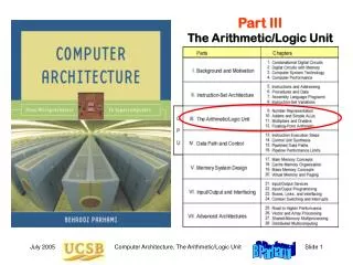
Part III The Arithmetic/Logic Unit
Part III The Arithmetic/Logic Unit. III The Arithmetic/Logic Unit. Overview of computer arithmetic and ALU design: Review representation methods for signed integers Discuss algorithms & hardware for arithmetic ops Consider floating-point representation & arithmetic.

Part III The Arithmetic/Logic Unit
E N D
Presentation Transcript
Part IIIThe Arithmetic/Logic Unit Computer Architecture, The Arithmetic/Logic Unit
III The Arithmetic/Logic Unit • Overview of computer arithmetic and ALU design: • Review representation methods for signed integers • Discuss algorithms & hardware for arithmetic ops • Consider floating-point representation & arithmetic Computer Architecture, The Arithmetic/Logic Unit
10 Adders and Simple ALUs • Addition is the most important arith operation in computers: • Even the simplest computers must have an adder • An adder, plus a little extra logic, forms a simple ALU Computer Architecture, The Arithmetic/Logic Unit
10.1 Simple Adders Digit-set interpretation: {0, 1} + {0, 1} = {0, 2} + {0, 1} (x + y = c + s) Digit-set interpretation: {0, 1} + {0, 1} + {0, 1} = {0, 2} + {0, 1} (x + y + cin = cout + s) Figures 10.1/10.2 Binary half-adder (HA) and full-adder (FA). Computer Architecture, The Arithmetic/Logic Unit
Full-Adder Implementations Figure10.3 Full adder implemented with two half-adders, by means of two 4-input multiplexers, and as two-level gate network. Computer Architecture, The Arithmetic/Logic Unit
Critical path Ripple-Carry Adder: Slow But Simple Figure 10.4 Ripple-carry binary adder with 32-bit inputs and output. Computer Architecture, The Arithmetic/Logic Unit
10.2 Carry Propagation Networks gi = xiyi pi = xiyi Figure 10.5 The main part of an adder is the carry network. The rest is just a set of gates to produce the g and p signals and the sum bits. Computer Architecture, The Arithmetic/Logic Unit
Ripple-Carry Adder Revisited The carry recurrence: ci+1 = gipici Latency of k-bit adder is roughly 2k gate delays: 1 gate delay for production of p and g signals, plus 2(k – 1) gate delays for carry propagation, plus 1 XOR gate delay for generation of the sum bits Figure 10.6 The carry propagation network of a ripple-carry adder. Computer Architecture, The Arithmetic/Logic Unit
First Carry Speed-Up Method: Carry Skip Figures 10.7/10.8 A 4-bit section of a ripple-carry network with skip paths and the driving analogy. Computer Architecture, The Arithmetic/Logic Unit
Θ(log n)-time Recursive Wired-OR Carry-Skip Adder With this recursive structure, we can do a 2n-bit add in 2(n+1)logic levels. Hardwareoverhead is< 2× regularripple-carry! (8 bit segment shown) Cin S A B S A B S A B S A B S A B S A B S A B S A B G Cin GCoutCin GCoutCin G Cin GCoutCin G Cin GCoutCin G Cin P P P P P P P P PmsGlsPls Pms GlsPls PmsGlsPls Pms GlsPls MS MS LS LS G G GCout Cin GCout Cin P P P P Pms GlsPls Pms GlsPls MS LS G GCout Cin P P Pms GlsPls LS GCout Cin P
10.3 Counting and Incrementation Figure 10.9 Schematic diagram of an initializable synchronous counter. Computer Architecture, The Arithmetic/Logic Unit
Circuit for Incrementation by 1 Substantially simpler than an adder Figure 10.10 Carry propagation network and sum logic for an incrementer. Computer Architecture, The Arithmetic/Logic Unit
h j i i+1 10.4 Design of Fast Adders Carries can be computed directly without propagation For example, by unrolling the equation for c3, we get: c3 = g2p2c2 = g2p2g1p2p1g0p2p1p0c0 We define “generate” and “propagate” signals for a block extending from bit position a to bit position b as follows: g[a,b] = gbpbgb–1 pbpb–1gb–2 . . . pbpb–1…pa+1 ga p[a,b] = pbpb–1. . . pa+1 pa Combining g and p signals for adjacent blocks: g[h,j] = g[i+1,j]p[i+1,j]g[h,i] p[h,j] = p[i+1,j]p[h,i] [h, j] = [i + 1, j] ¢ [h, i] Computer Architecture, The Arithmetic/Logic Unit
Second Carry Speed-Up Method: Carry Lookahead [a,b]=For bitsfrom positionsa through b Figure 10.11 Brent-Kung lookahead carry network for an 8-digit adder, along with details of one of the carry operator blocks. Computer Architecture, The Arithmetic/Logic Unit
Recursive Structure of Brent-Kung Carry Network Figure 10.12 Brent-Kung lookahead carry network for an 8-digit adder, with only its top and bottom rows of carry-operators shown. Computer Architecture, The Arithmetic/Logic Unit
Carry-Lookahead Logic with 4-Bit Block Figure 10.13 Blocks needed in the design of carry-lookahead adders with four-way grouping of bits. Computer Architecture, The Arithmetic/Logic Unit
Third Carry Speed-Up Method: Carry Select Allows doubling of adder width with a single-mux additional delay (Carry in to position a) Figure 10.14 Carry-select addition principle. Computer Architecture, The Arithmetic/Logic Unit
10.5 Logic and Shift Operations Conceptually, shifts can be implemented by multiplexing Figure 10.15 Multiplexer-based logical shifting unit. Computer Architecture, The Arithmetic/Logic Unit
Arithmetic Shifts Purpose: Multiplication and division by powers of 2 sra $t0,$s1,2 #$t0($s1) right-shifted by 2 srav $t0,$s1,$s0 #$t0($s1) right-shifted by ($s0) Figure 10.16 The two arithmetic shift instructions of MiniMIPS. Computer Architecture, The Arithmetic/Logic Unit
Practical Shifting in Multiple Stages Figure 10.17 Multistage shifting in a barrel shifter. Computer Architecture, The Arithmetic/Logic Unit
Bit Manipulation via Shifts and Logical Operations AND with mask to isolate a field: 0000 0000 0000 0000 1111 1100 0000 0000 Right-shift by 10 positions to move field to the right end of word The result word ranges from 0 to 63, depending on the field pattern Figure 10.18 A 4 8 block of a black-and-white image represented as a 32-bit word. Computer Architecture, The Arithmetic/Logic Unit
Logic unit 0 Arith unit 1 10.6 Multifunction ALUs Logic fn (AND, OR, . . .) Operand 1 Result Operand 2 Select fn type (logic or arith) Arith fn (add, sub, . . .) General structure of a simple arithmetic/logic unit. Computer Architecture, The Arithmetic/Logic Unit
An ALU for MiniMIPS Figure 10.19 A multifunction ALU with 8 control signals (2 for function class, 1 arithmetic, 3 shift, 2 logic) specifying the operation. Computer Architecture, The Arithmetic/Logic Unit


![RESOURCE MATERIALS ON JNVST [JAWAHAR NAVODAYA VIDYALAYA SELECTION TEST]](https://cdn3.slideserve.com/6473750/resource-materials-on-jnvst-jawahar-navodaya-vidyalaya-selection-test-dt.jpg)