Introduction to a Simple Computer
Introduction to a Simple Computer. Nizamettin AYDIN naydin@y ildiz .edu.tr http:// www . yildiz .edu.tr/~naydin. What is a computer? in terms of what? Functional Structural. Function. All computer functions are: Data processing Data storage Data movement Control. Computer.

Introduction to a Simple Computer
E N D
Presentation Transcript
Introduction to a Simple Computer Nizamettin AYDIN naydin@yildiz.edu.tr http://www.yildiz.edu.tr/~naydin
What is a computer? • in terms of what? • Functional • Structural
Function • All computer functions are: • Data processing • Data storage • Data movement • Control
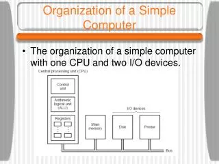
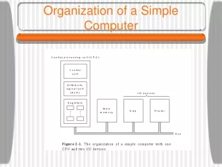
Computer Peripherals Central Processing Unit Main Memory Computer Systems Interconnection Input Output Communication lines Structure - Top Level
CPU Arithmetic and Logic Unit Computer Registers I/O System Bus CPU Internal CPU Interconnection Memory Control Unit Structure - The CPU
Control Unit CPU Sequencing Logic ALU Control Unit Internal Bus Control Unit Registers and Decoders Registers Control Memory Structure - The Control Unit
Fundamental computer elements Data storage: Provided by memory cells Data processing: Provided by gates Data movement: The paths between components are used to move data from/to memory Control: The paths between components can carry control signals
Levels of Representation lw $15, 0($2) lw $16, 4($2) sw $16, 0($2) sw $15, 4($2) temp = v[k]; v[k] = v[k+1]; v[k+1] = temp; High Level Language Program Compiler Assembly Language Program Assembler 0000 1001 1100 0110 1010 1111 0101 1000 1010 1111 0101 1000 0000 1001 1100 0110 1100 0110 1010 1111 0101 1000 0000 1001 0101 1000 0000 1001 1100 0110 1010 1111 Machine Language Program Machine Interpretation Control Signal Specification ALUOP[0:3] <= InstReg[9:11] & MASK ° °
Program Concept • Hardwired systems are inflexible • General purpose hardware can do different tasks, given correct control signals • Instead of re-wiring, supply a new set of control signals
What is a program? • A sequence of steps • For each step, an arithmetic or logical operation is done • For each operation, a different set of control signals is needed • For each operation a unique code is provided • e.g. ADD, MOVE • A hardware segment accepts the code and issues the control signals • We have a computer!
Components • The Control Unit and the Arithmetic and Logic Unit constitute the Central Processing Unit • Data and instructions need to get into the system and results out • Input/output • Temporary storage of code and results is needed • Main memory
CPU Structure • CPU must: • Fetch instructions • Interpret instructions • Fetch data • Process data • Write data
Registers • CPU must have some working space (temporary storage) • Called registers • Number and function vary between processor designs • One of the major design decisions • Top level of memory hierarchy
Registers in the P perform two roles: • User-visible registers • Enable the machine- or assembly language programmer to minimize main memory references by optimizing use of registers • Control and status registers • Used by the control unit to control the operation of the processor and by priviliged, operating system programs to control the execution of programs
User Visible Registers • General Purpose registers • Data registers • Address registers • Condition Codes (flags)
Condition Code Registers • Sets of individual bits • e.g. result of last operation was zero • Can be read (implicitly) by programs • e.g. Jump if zero • Can not (usually) be set by programs
Control & Status Registers • Program Counter (PC) • Contains the address of an instruction to be fetched • Instruction Decoding Register (IR) • Contains the instruction most recently fetched • Memory Address Register (MAR) • Contains the addres of location in memory • Memory Buffer Register (MBR) • Contains a word or data to be written to memory or the word most recently read
Program Status Word • A set of bits containing status information • Includes Condition Codes (flags) • Sign • sign of last result • Zero • set when the result is 0 • Carry • set if an operation resulted in a carry (addition) into or borrow (subtraction) out of a high order bit • Equal • set if a logical compare result is equality • Overflow • used to indicate arithmetic overflow • Interrupt enable/disable • used to enable or disable interrupts
Operation of Memory • Each memory location has a unique address • Address from an instruction is copied to the MAR which finds the location in memory • CPU determines if it is a store or retrieval • Transfer takes place between the MDR and memory • MDR is a two way register
Data Address Relationship between MAR, MDR and Memory
Memory Capacity • Determined by two factors 1. Number of bits in the MAR • 2K where K = width of the register in bits 2. Size of the address portion of the instruction • 4 bits allows 16 locations • 8 bits allows 256 locations • 32 bits allows 4,294,967,296 or 4 GB • Important for performance • Insufficient memory can cause a processor to work at 50% below performance
RAM: Random Access Memory • DRAM (Dynamic RAM) • Most common, cheap • Volatile: must be refreshed (recharged with power) 1000’s of times each second • SRAM (static RAM) • Faster than DRAM and more expensive than DRAM • Volatile • Frequently small amount used in cache memory for high-speed access used
ROM - Read Only Memory • Non-volatile memory to hold software that is not expected to change over the life of the system • Magnetic core memory • EEPROM • Electrically Erasable Programmable ROM • Slower and less flexible than Flash ROM • Flash ROM • Faster than disks but more expensive • Uses • BIOS: initial boot instructions and diagnostics • Digital cameras
Bus • The physical connection that makes it possible to transfer data from one location in the computer system to another • Group of electrical conductors for carrying signals from one location to another • Line: each conductor in the bus • 4 kinds of signals • Data (alphanumeric, numerical, instructions) • Addresses • Control signals • Power (sometimes)
Bus • Connect CPU and Memory • I/O peripherals: on same bus as CPU/memory or separate bus • Physical packaging commonly called backplane • Also called system bus or external bus • Example of broadcast bus • Part of printed circuit board called motherboard that holds CPU and related components
Bus Characteristics • Protocol • Documented agreement for communication • Specification that spells out the meaning of each line and each signal on each line • Throughput, i.e., data transfer rate in bits per second • Data width in bits carried simultaneously
Point-to-point vs. Multipoint Plug-in device Broadcast bus Example: Ethernet Shared among multiple devices
Motherboard • Printed circuit board that holds CPU and related components including backplane
Typical PC Interconnections Bus interface bridges connect different bus types
Instructions • Instruction • Direction given to a computer • Causes electrical signals to be sent through specific circuits for processing • Instruction set • Design defines functions performed by the processor • Differentiates computer architecture by the • Number of instructions • Complexity of operations performed by individual instructions • Data types supported • Format (layout, fixed vs. variable length) • Use of registers • Addressing (size, modes)
Source OPERAND Result OPERAND OPCODE InstructionElements • OPCODE: task • Source OPERAND(s) • Result OPERAND • Location of data (register, memory) • Explicit: included in instruction • Implicit: default assumed Addresses
Instruction Format • Machine-specific template that specifies • Length of the op code • Number of operands • Length of operands Simple 32-bit Instruction Format
Instruction Types • Data Transfer (load, store) • Most common, greatest flexibility • Involve memory and registers • What’s a word? 16? 32? 64 bits? • Arithmetic • Operators + - / * ^ • Integers and floating point • Logical or Boolean • Relational operators: > < = • Boolean operators AND, OR, XOR, NOR, and NOT • Single operand manipulation instructions • Negating, decrementing, incrementing
More Instruction Types • Bit manipulation instructions • Flags to test for conditions • Shift and rotate • Program control • Stack instructions • Multiple data instructions • I/O and machine control
Program Control Instructions • Program control • Jump and branch • Subroutine call and return
Instruction Cycle • Two steps: • Fetch • Execute
Fetch Cycle • Program Counter (PC) holds address of next instruction to fetch • Processor fetches instruction from memory location pointed to by PC • Increment PC • Unless told otherwise • Instruction loaded into Instruction Register (IR) • Processor interprets instruction and performs required actions
Execute Cycle • Processor-memory • data transfer between CPU and main memory • Processor I/O • Data transfer between CPU and I/O module • Data processing • Some arithmetic or logical operation on data • Control • Alteration of sequence of operations • e.g. jump • Combination of above
A simple example – • Next figure illustrates a partial program execution. • It adds the contents of the memory word at address 940 to the contents of the memory word at address 941 and stores the result in the address 941. • Here 3 instructions (3 fetch and 3 execute cycles) are required