LEReC
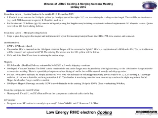
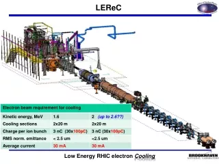
LEReC. LEReC layout. 63.9 m to IP2. Commissioning Diagnostic Line 1. 704 SRF Booster Cavity. Commissioning Diagnostic Line 2. DC e - Gun. 2.1 GHz Cu Cavity. 704 MHz Cu Cavity. 9 MHz Cu Cavity. e -. e -. COOLING in Yellow RHIC ring. RHIC TRIPLET. RHIC DX. e -. COOLING

LEReC
E N D
Presentation Transcript
LEReClayout 63.9 m to IP2 Commissioning Diagnostic Line 1 704 SRF Booster Cavity Commissioning Diagnostic Line 2 DC e- Gun 2.1 GHz Cu Cavity 704 MHz Cu Cavity 9 MHz Cu Cavity e- e- COOLING in Yellow RHIC ring RHIC TRIPLET RHIC DX e- COOLING in Blue RHIC ring LEReC Solenoids Compensating (LF) Matching (HF) Merger/Transport 180° Bending Magnet Beam Dump 20° Bending Magnets
LEReC Meetings LEReC Beam Physics & Lattice LEReC Cathodes: usually Fridays bi-weekly C.J. Liaw, JT LEReC DC Gun: Phone conference with Cornell usually Fridays, bi-weekly C.J. Liaw LEReC DC Gun to Booster Cavity: bi-weekly, S. Nayak LEReC Booster Cavity Modification, K. Smith LEReC Diagnostic Beam Line: weekly, K. Smith LEReC warm RF Cavities: Vendor phone conferences, tuner and window design, A. Zaltsman LEReC beam diagnostics: weekly, T. Miller LEReC transport and cooling beam lines: bi-weekly, JT Cooling section loose ends, transport instrumentation (for DC Gun)
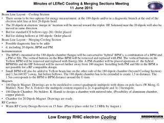
Cooling Section Installation RHIC Components moved and operational in their new locations! Cooling section vacuum and magnets installed. Work to complete: Profile Monitors (4) assemble and test Emittance slits (2) assemble and test BPM buttons – 2 damaged during installation Emittance slit vacuum chamber leak
Cooling Section 2016 or 2017 Installations Standard Profile Monitor Assemblies (4) (2 chambers held for drive testing) 180o Magnet Assembly Magnet (magnetic measured) Hybrid PM/ES/BPMAssemblies (2) Vacuum chamber (measured) Magnetic field monitoring (characterized) Stand (non-moving) Bellows assemblies Add Std. BPM/ move solenoid Emittance Slit Assemblies (2) (Chamber held for drive testing) Magnet shielding test assembly April DOE Review: Test Set-ups Complete
2016 Schedule Update Installation of the DC eGun in 02:00 to commissioning with beam during the 2017 RHIC run has become the project priority. Cathode insertion mechanism/develop a cathode production system DC eGun to Booster cavity transport line. Laser transport, laser table with temperature control, communications Controls, communications, MPS, ACS, trays, water, power, cleanrooms Temporary beamline in place of the Booster cavity. First section of the high energy transport line: magnets, PS, vacuum, etc. First diagnostic line with faraday cup/beam dump.
DC Gun DC Gun & Commissioning Transport Line LEReC Profile Monitor ERL Beam Dump 704 SRF Cavity (not installed) ERL Solenoid? ERL Emittance Slit 20° dipole Gun to Booster Cavity Transport line installed 2.1 GHz Cavity LEReC Profile Monitor ERL Solenoid Merger Solenoid ERL Halo Monitors & Pick-ups ERL DCCT ERL ICT ERL Solenoid DCCT ICT BPM BPM ID 1.87
Gun to Booster Laser trace for 6mm laser spot offset • Relocated laser mirrors • Redesigned and Relocated Solenoid and Corrector Magnets • Relocated BPM’s and Profile Monitor Added clearing electrodes (updated BPM buttons) Redesign DC Gun Anode Redesign Booster Cavity upstream end Need to add remove adjustment for solenoids.
DC Gun Installation (- Booster Cavity) Need • Transport Laser line, laser table • 2.1 GHz coax/waveguide • Work platform for DC gun access • Cable tray, water, power for DC gun and 2.1 GHz • Clean rooms • Co-exist with CeC components 2017
Diagnostics: Gun to Booster Cavity Equipment specifications: • Solenoids, Dipole, BPM’s • Beam diagnostics hardware and electronics • Beam line vacuum Extracted Laser 2 Solenoid(s) D&M Correctors (2) BPM’s (2) Phase PU Clearing Electrodes YAG BPM BPM BPM Faraday Cup YAG YAG BPM BPM DC Gun (Photocathode) DCCT Injection BPM = 6 YAG = 3 ICT = 1 DCCT = 1 Emittance Slit = 1 Halo Pairs = 2 Faraday Cup (& pick-ups) = 5 704 MHz SRF Booster Em-Slit ICT Vertical & Horizontal Halo Monitors & Pick-Ups Laser Injection Port Laser Optics Table 2.1 GHz Warm Cavity Cornell Layout GtB – modify for offset laser spot Bake-out to 200C near DC Gun DC Gun instrumentation: • Large Button or ERL Buttons or Striplines?? • Profile Monitor in Laser Cross • Cathode Camera in Laser Cross
Transport Line Instrumentation Analysis, mechanical design, and procure components for entire transport line. Assemble, test, and install components needed for DC gun commissioning. BPM chamber assemblies and stands (new or ERL buttons?) Profile monitor vacuum chambers (ERL drive assemblies) Emittance slits (ERL parts?) Halo monitor Faraday cup for diagnostic line 1 DCCT and ICT
2016 Schedule (No Change) Installation of both new warm RF cavities at 02:00 with the goal of commissioning both during the 2017 RHIC run. Design and procure both 2.1 GHz and 704 MHz cavities Procure and install PA’s Design and fabricate tuners for both with drive system and controls. Procure RF windows and vacuum transition components Design (route), procure, and install coax/waveguide Installation stands, water, cable tray, etc. Determine if 2.1 GHz cavity can be installed in “final” position. Install 9 MHz cavity if possible.
2.1 GHz Cavity Cavity fabrication contract awarded, first vendor meeting yesterday. Windows ordered, Jlab tested. Aluminum cavity testing underway Tuner design underway Vacuum wave guide and wave guide Stand assembly design
704 MHz Cavity Cavity fabrication requisition prepared Drawing revision for frequency change RFP out – Bids due 2/5/15 Tuner design Window design
2017 Installation – Long Lead Items Booster Cavity Conversion Cryogenic system installation for the Booster Cavity Diagnostic line 2, AKA commissioning beam line. 704 MHz “deflecting” RF Cavity Fast beam kicker system with beam dump Spectrometer deflector system Spectrometer faraday cup/beam dump Beam line (transport) components: magnets, PS, diagnostics, vacuum, stands Controls, communications, cable tray Cathode production system
Commissioning Beam Line Need dump design May need to kick beam out of transport for defocusing optics and proper beam dump Corrector added before deflecting cavity BPM added after deflecting cavity Single Layer Mu-Metal shielding should be installed Simulations & calculations suggest instrument sensitivity exceeds requriements for cooling Confirmation from AP pending... Cost & schedule estimate needed in 2 weeks! Beam Sampling Technique for high power single macro bunch measurements YAG & Slit HVDC Deflector Solenoid From Transport Section To Merger Section Faraday Cup Medium Power Beam Dump (Full Power ~250μs) Fixed YAG Scanning YAG Profile Monitor LASER Deflecting Cavity (704MHz) Commissioning B/L YAG = 3 Faraday Cup = 1 Defining Slit = 1 Beam Sampling Technique: Dumps all beam before RF cavity steady state condition is reached; thereby providing low average power samples representative of steady state high power beam. Kicker RF Settling Time ~250μs Full power on dump Instrumentation Exposure ~10μs
19.68” 72.87” 99.41” 49.90” 67.62”
April 2016 – DOE “Mini” Review Schedule update with revised milestones highlighting DC gun installation. Project Change Request for Diagnostic Line 2 Funds Cost estimate in 2 weeks: 704 MHz “deflecting” RF Cavity (Zaltsman, Smith, Brutus) Fast beam kicker system with beam dump (Mernick, Hock) Spectrometer deflector system (Thieberger, Miller, Hock) Spectrometer faraday cup/beam dump (Miller) Beam line (transport) components: magnets, PS, diagnostics, vacuum, stands (Hock, Mahler, Bruno, Miller, Mapes) Internal: Cathode production system schedule and cost (Rao, Tuozzolo, Liaw, Hamdi)
LEReC Cooling Section Design Room LF & HF solenoid and 20o dipole magnets fabrication drawings(KH) Beam Diagnostics: BPM chamber and buttons (VDM) Beam Line 5” bellows with shields fabrication drawings (GW) 20o dipole vacuum chamber for impedence review (KH) 180o dipole fabrication drawings (KH) Spectrometer magnet (180o dipole) revisions (KH) 180o vacuum chamber + large sliding bellows fabrication drawing (KH) Beam Diagnostics ES W slit & chamber fabrication drawings (VDM) 20o dipole vacuum chamber fabrication drawings (KH) Cable tray and penetration drawings and excel sheet (AF) Beam Diagnostics: PM vacuum chamber fabrication drawings (GW) Beam Diagnostics: standard PM fabrication drawings (GW) Beam Diagnostics: special “hybrid” ES/PM/BPM fabrication drawings (GW) Beam line solenoid/BPM stands & vacuum chamber stand (VDM) 20o magnet stand drawing (KH) 180o magnet w/hybrid assembly BPM stand drawings (KH), add BPM?? on hold Magnetic shielding drawing and solenoid magnetic measurement test station (VDM) In tunnel, magnetic measurement “mole” for stray field studies Quadrupole and skew quadrupole correctors for HF dipoles
LEReC Design Room Source Design Work DC Gun Vacuum Chamber Fabrication Drawings (JH) DC Gun SF6 Pressure chamber specification control drawings (JH) DC Gun cathode cooling design for Karl S. Cornell (JH) DC Gun stands (JH) DC Gun to SRF booster cavity beam line (JH) DC Gun to SRF booster cavity laser port, view port, profile monitor (JH) DC Gun to SRF booster cavity solenoid/corrector magnets (JH) DC Gun to SRF booster cavity BPM’s DC Gun cathode insertion drive assembly ERL Gun to Booster Cavity Modifications: U/S cathode to beam tube, FPC, D/S beamline & HOM (SS, JH) Cathode coating system cathode bakeout vacuum chamber & heater (KH & BM) Cathode coating system deposition vacuum chamber w/internal cathode transport system (KH) Cathode coating system transport vacuum chamber – ferris wheel (KH & WJ)
LEReC Design Room Other Work RHIC 1:00 move real estate drawings (V.DM.) Cryogenic system layout (RM) 2.1 GHz warm cavity spec. control drawings (MG) 2.1 GHz warm cavity tuner, wave guide, and warm test model (MG) 704 MHz warm cavity spec. control drawings (SP) Transport & Merger line layout (RM, KH) Locate booster cavity, solenoids, BPM’s, RF Cavities, PM’s, Diagnostic Lines Transport & Merger Line Solenoids (KH) Transport Line Solenoid Stands Transport & Merger Line Bellows and Pump Ports (GW) Transport & Merger Line CT’s (GW) Transport & Merger Line BPM’s (GW) Transport & Merger Line Correctors Transport & Merger Line Profile Monitors Merger Line Flying Wire Diagnostic Beam Lines and Components Kickers, RF cavity, beam dump,
Diagnostics: Transport YAG BPM BPM BPM BPM BPM BPM BPM BPM 2.1 GHz Warm Cavity 704 MHz Warm Cavity 704 MHz Warm Cavity Solenoid(s) 11 locations Quadrapole(s) 2 locations Beam pipe size 2.38 ID does not match ERL Bake-out to near RHIC and near Booster Cavity?? ERL Buttons for BPM’s OK?? Profile Monitor drives from ERL, vacuum chamber? ERL emittance slit drive Commissioning line dipole angle 2nd 2.1 GHz cavity location? Another 20o dipole? e-Beam Transport BPM = 8 YAG = 1
Commissioning Beam Line Beam Sampling Technique for high power single macro bunch measurements YAG & Slit HVDC Deflector Solenoid From Transport Section To Merger Section Faraday Cup Medium Power Beam Dump (Full Power ~250μs) Fixed YAG Scanning YAG Profile Monitor Deflecting Cavity (704MHz) Separate Group Meeting Kicker TBS Merger solenoid?? Internal beam dump TBD Deflecting cavity design underway HVDC deflector TBD Another 20o dipole? TBD Fixed and Scan YAG’s dumps Commissioning B/L YAG = 3 Faraday Cup = 1 Defining Slit = 1
Merger/Transport Merger Solenoid BPM Corrector Gate Valve Quadrupole Bellows 20° dipole Need Quadrupole Magnet Spec’s Same as dump quadrupole? Move gate valve down stream of 20o? Instrumentation line Profile Monitor Wire Scanner Profile Monitor 9 MHz Cavity 704 Cavity Triplet Quadrupole Profile Monitor Gate Valve 20° dipole Beam Dump Quadrupole
IP 02:00 Profile Monitor Emittance Slit Merger Solenoid Profile Monitor 2.1 GHz Cavity 20° dipole Commissioning line