Download
1 / 24
240 likes | 252 Vues
This document discusses various topics related to the beam line layout of the LEReC cooling and merging sections, including energy measurement options, instrumentation changes, magnet modifications, and RF cavity design.

E N D
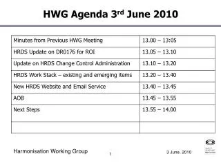
Minutes of LEReC Cooling & Merging Sections Meeting11 June 2015 Beam Line Layout – Cooling Section There seems to be two options for energy measurement: at the 180 dipole and/or in a diagnostic branch at the end of the electron inlet line at first 20 dipole bend. The 20 dipole at electron ‘merge in’ location will be moved toward the triplet. HF Solenoid near the 20 dipole will also be moved in same direction. Bid for standard CS bellows (qty-26): Order placed. Bid for sliding bellows at 180 dipole: Order placed. Beam Line Layout – Merging Cooling Section Possible diagnostic line to be adde d, including 20 dipole, BPM and PM. Instrumentation The BPM’s mounted at the 180 dipole chamber flanges will be converted to ‘hybrid’ BPM’s, a combination of a BPM and a PM or Slit. The vertical buttons on the Blue BPM will be removed and replaced with PM. The vertical buttons on the Yellow BPM will be removed and replaced with Energy Slit. A PM chamber will be placed upstream of the hybrid BPM/Slit and the HF Solenoid will be moved further away from 180 magnet. Installing both PM and Slit in the BPM is not possible for a RF compatible design. Small BPM will also be added to Yellow beam line on the other side of the 180 dipole chamber (beyond Cooling Section) and 1.5m (60.85”) away, but before bellows. The 180 dipole chamber has to be extended to create 1.5 m distance. The 1.5m corresponds to the BPM to BPM distance around the U-turn. Magnets 180 Dipole Magnet: Drawings are to be modified to correct quadrupole multipole with shims on pole faces (W.Meng, G. Mahler). Note: Per A. Fedotov the multipole content required is 2e-4 quadrupole and 3e-3 hextapole. 180 Dipole Chamber: No bidders. K. Hamdi to design a chamber with mitered tube. (Possibility of aluminum chamber, copper plated). Chamber for 20 Dipole Magnet: Drawings are ready. RF Cavities Warm RF Cavity Design Review on 15 June. (Plan to place order for 2.1MHz by August.)
Overall Layout 64 m IP2 LEReC-I (1.6-2MeV): Gun to dump SRF gun used as a booster cavity H & V Correctors Add Quad and Skew Quad Correctors Move BPM close to 180 magnet combine with PM. Add Quad and Skew Quad Correctors
180o Dipole Magnet Neighborhood II Small Aperture BPM’s Both with PM’s ?? HIGH FIELD SOLENOID WINDOW FRAME H&V CORRECTORS LOW FIELD SOLENOIDS w/H&V Corrector ± 4.13” Standard BPM’s Remove H&V PROFILE MONITOR? EMITTANCE SLIT PROFILE MONITOR WINDOW FRAME Quad and Skew Quad CORRECTOR New Horizontal PROFILE MONITOR K Hamdi
180o Dipole Magnet Neighborhood III Add Profile Monitor
BPMs in Cooling Section (14 Locations) Large Dia. BPM Housings (4.8 ID), 28mm buttons Order Placed with MPF Vendor’s Project Schedule 1st Article Button(s) 10/5/15 3 month housing fabrication Housing fabrication start 10/12/15 Increase number of button first articles Start housing fabrication now Special ID for 180 Magnet Same button size, Analysis OK Eliminate vertical button for PM Combined with Profile Monitor, Add single emittance slit, impedance??, ferrite location??
Compensating and Matching Solenoids Buckley magnets complete 8/20/2015 + 6 weeks shipping + customs. Alpha Magnetics update: We have started winding the trim coils and we are machining all the parts, the only materials I don’t have yet is the main coil wire yet… should be here next week. Ken Wadsworth Alpha Magnetics Design support stand assembly – provide space for mu metal shields, separate beam pipe stand support. Magnetic shielding analysis (Wuzheng) Design prototype mu metal shields and supports. Magnet measurement fixture plan for prototype and design test fixtures.
Cooling Section Profile Monitors Ferrite ring mounting design complete. CMD5005 material. Requisition for commercial vacuum linear stage, requisition complete YAG screen/mirror holder design complete. Fabrication drawings for YAG screen/mirror holder and vacuum chamber Revise RF impedance design Stage Assembly (Linear Feedthrough) Zero Length adapter flange Profile Monitor YAG Screen Assy.
Cooling Section Profile Monitors Revise RF impedance redesign: remove ferrite install RF fingers.
Cooling Section Emittance Slits Motor drives and position indication specs. approved by vendor. Requisition for commercial vacuum linear stage? Tungsten plate vendor, design adapter tungsten plate to drive shaft flange.
180o Dipole Magnet Requisition Status Range of motion for magnet core +/- 10cm. Magnet Vertical Gap = 10.0 cm (3.94 in.) Vacuum Chamber Aperture = 9.5 cm (3.75 in.)
Vacuum Hardware Beam line bellows & 180 accordion bellows requisition status. “Standard Chamber Length” 180 chamber 316L vacuum annealed to 900C after welding. Test chamber welded and measured. Annealing Shielded valves on order, need DC Gun shielded valves.
20o Dipole Magnet Requisition approved SOW – 2 magnets by 10/1/2015. Order Placed 5/6/2015 Everson Tesla Estimated Delivery 1st two magnets 10/1/2015 Distance Between Pole Faces = 10.4 cm (4.1 in.) Magnet Vertical Gap = 10 cm Vacuum Chamber V Aperture = 9.5 cm (3.74 in.)
20o Dipole Magnet Vacuum Chamber Here attached the wake field analyses of the 180 degree and 20 degree chambers for LEReC. The 180 degree chamber shows a wake loss factor at 0.0186 V/pc, and for the 20 degree chamber, it is 0.0295. Best,Binping Fabrication Drawing
LEReC Cooling Section Design Room Design 180o dipole chamber for impedance review (KH) LF & HF solenoid and 20o dipole fabrication drawings(KH) BPM chamber and buttons (VDM) Beam Line 5” bellows with shields fabrication drawings (GW) 20o dipole vacuum chamber for impedence review (KH) 180o dipole fabrication drawings (KH) 180o vacuum chamber + large sliding bellows fabrication drawing (KH) Beam Instrumentation ES W slit & chamber fabrication drawings (VDM) Beam Instrumentation PM YAG, mirror, mount, & chamberfab. drawings (GW) Beam Instrumentation PM ferrite insert (GW) 20o dipole vacuum chamber (KH) 20o and 180o stand drawings (KH) Beam line solenoids, BPM’s, and long pipe independent stands. Magnetic Shielding drawing and solenoid magnetic measurement test station Cable tray and penetration drawings
LEReC Design Room Phase 2: 5 cell cavity positioning (RM) DC Gun Vacuum Chamber Fabrication Drawings (JH) DC Gun SF6 Pressure chamber specification control drawings (JH) DC Gun to Booster SRF booster cavity beam line (JH) DC Gun & SF6 Chamber stands (JH) RHIC 1:00 move real estate drawings (VDM) Phase 2: 5 cell cavity positioning (RM) – Revised Position Phase 1 and 2 cryogenic system layout (RM) 2.1 GHz warm cavity fabrication drawings (MG) 704 MHz warm cavity fabrication drawings DC Gun cathode insertion drive DC Gun cathode coating system upgrade – coating system vacuum chamber Transport line layout drawing (RM/VDM)
180o Dipole Magnet Neighborhood II Aperture Transitions
5 cell cavity location New updates? 5 cell
LEReC Dipole Skew Quad Corrector • Window-frame Skew Quad: 100 A-turn per corner = s-quad gradient 3.19 G/cm or, 3.19E-2 T/m • Current polarities: • Opposite corners have the same polarity • Adjacent corners have the opposite polarities.
Sector 2 Modifications LEReC: • Move cable tray/Modify cable tray • Move Access Controls Gate • Remove stairway and part of cross-over platform • Tunnel Penetrations