Download
1 / 1
10 likes | 84 Vues
Developing compact inertial sensors for high-frequency feedback in a 1 TeV linear collider environment. Requirements include low noise, compact size, and non-magnetic materials. Initial tests and technical challenges outlined.

E N D
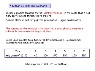
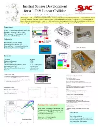
The proposed 1 TeV X-band electron / positron linear collider will produce beams with approximately 1 nanometer vertical sizes at the collision point. The final focusing magnets for this accelerator must be held relative to each other at the nanometer level. Beam – Beam interactions provide a signal for a high gain feedback for frequencies below ~1Hz, but additional stabilization is required at higher frequencies. One option is to use inertial sensors (geophones) to provide a feedback signal. Inertial Sensor Development for a 1 TeV Linear Collider Requirements Noise: < 1 nanometer integrated above 1Hz. Frequency response: 0.1Hz to 50Hz. Must operate in 1 Tesla magnetic field Compact - ~20×20×10 cm Technology: RF capacitive position sensing Position feedback through DSP Feedback force -> measured acceleration BeCu spring, Ceramic moving parts Prototype sensor Parameters Test mass 40 grams Suspension frequency 1.5Hz Mechanical Q >100 Theoretical thermal mechanical noise <1.5×10⁻¹⁰M/s2/Hz1/2. Capacitor Sensor gap ~300 microns Theoretical thermal electronic noise < thermal noise Vacuum <few microns Eric Doyle, Josef Frisch, Linda Hendrickson, Thomas Himel, Thomas Markieweicz, Justin May, Richard Partridge, Andrei Seryi Work Supported by Department of Energy Contract DE-AC03-76SF0515 Technical Issues: Creep Spring must be operated at high stress to maximize unwanted 2nd mode frequency (from ANSYS simulations) Lifetime of sensor limited by creep of spring. Tests at design 75% of yield stress give creep life >20 years. Creep chart Technical Issues: Magnetic sensitivity Housing, fixed supports: Non-magnetic stainless, Aluminum Motor: (for creep / temperature compensation) Piezoelectric motor (PicomotorTM), nonmagnetic in final system Cantilever: Prototype uses Aluminum cantilever. (conductor: dB/dt problem) Final version uses Aluminum Oxide cantilever Mass: Tungsten in prototype (magnetic in first prototype!) Final version: HfO2 9.8g/cc, (heaviest non-radioactive ceramic) Technical Issues: Creak High spring stress can produce creak Also ,early prototype had problems with creak in support components (support position pot) Technical Issues: Temperature Sensitivity Non-magnetic requirement prevents the use of temperature compensated spring materials. Calculated temperature sensitivity ~.01 M/s2 / °C, 10 nano-degree temperature variation (during measurement time) would limit resolution. Design incorporates multiple thermal filters, gold plating for radiation shielding. Temperature variations probably major noise source below 0.1Hz. Preliminary Data – not verified! Initial testing of sensor vs. Strekheisen STS-2. Testing done in noisy lab environment: high Frequency noise (5-100Hz) exceeds sensor feedback actuator strength. Noise floor <~10-8m/s2/sqrt(Hz) Noise 1/f corner ~0.1Hz. Future Work: Test in quiet location Install fully non-magnetic components Try reduced spring stress to reduce creak. Add temperature stabilization