Download

1 / 41
410 likes | 590 Vues
International Linear Collider. Mike Spata February 24, 2010 Collider Review Retreat. Outline. Big Picture Upgrade Path Main Parameter Space Electron Injector Damping Rings Damping Ring to Linac Beamline Linac Positron Source Beam Delivery System Interaction Region

E N D
International Linear Collider Mike Spata February 24, 2010 Collider Review Retreat
Outline • Big Picture • Upgrade Path • Main Parameter Space • Electron Injector • Damping Rings • Damping Ring to Linac Beamline • Linac • Positron Source • Beam Delivery System • Interaction Region • SiD, LDC, GLD, 4th Detector Concepts • Detector Parameters
Big Picture • Polarized photocathode electron source (> 80% polarized) with Warm RF Buncher/Pre-Accelerator (76 MeV) • 5 GeV Superconducting Injector Linac • Electron and Positron Damping Rings (6.7 km circumference) • Beam transport from the damping rings to the main linacs, followed by a two-stage bunch compressor system prior to injection into the main linac • Undulator-based positron source powered by 150 GeV electrons • Two 11 km long main linacs, utilizing 1.3 GHz SCRF cavities, operating at an average gradient of 31.5 MV/m to accelerate the beams up to 500 GeV • 4.5 km long beam delivery system, which brings the two beams into collision with a 14 mrad crossing angle, at a single interaction point which can be shared by two detectors
Upgrade Path • Upgrade Positron source to produce polarized beams • Run facility as an e--e-Collider • Extend tunnels 11km for Energy upgrade to 1 TeV • Collide electrons at IP with a high energy laser beam to produce photons and operate as an e--γ or γ-γCollider
Basic Design Parameters a) Value at 500 GeV Center of Mass Energy
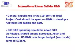
Technology Challenges • Beam instability and kicker hardware constraints in the damping rings • Beam current, beam power and pulse length limitations in the main linacs • Emittance preservation requirements, in the main linacs and in the beam delivery system; • Background control and kink instability issues in the interaction region.
Electron Injector • Functional Requirements • Generate the required bunch train of polarized electrons (> 80% polarization) • Capture and accelerate the beam to 5 GeV • Transport the beam to the electron damping ring with minimal beam loss, and perform • an energy compression and spin rotation prior to injection. Technical Challenges The SLC polarized electron source already meets the requirements for polarization, charge and lifetime. The primary challenge for the ILC electron source is the 1 ms long bunch train, which demands a laser system beyond that used at any existing accelerator.
Injector Optics Beam Transport along the 76 MeV Warm Injector
Injector Optics Beam Transport along the 5 GeV SRF Injector Linac Beam Envelope along the 76 MeV Warm Injector
Injector Optics Beam Transport from Booster Linac to Damping Ring
Damping Ring Layout • 6.7 km circumference • 6 arcs and 6 straight sections • Normal conducting transport system • 250 m of superconducting wigglers in each damping ring • 650 MHz RF system (1/2 linac frequency) • Arcs composed of TME cells to minimize quantum excitation • Straights composed of FODO cells to accommodate the damping wigglers, RF cavities and the injection/extraction regions • Two families of sextupoles within TME cells for chromatic correction • Technical Challenges • Control of the electron cloud effect in the positron damping ring. This effect, which can cause instability, tune spread, and emittance growth has been seen in a number of other rings and is relatively well understood. • Control of the fast ion instability in the electron damping ring. • Development of a very fast rise and fall time kicker for single bunch injection and extraction in the ring (3ns bunch spacing) • Functional Requirements • Accept e- and e+ beams with large transverse and longitudinal emittances and produce the low-emittance beams required for luminosity production • Damp incoming beam jitter (transverse and longitudinal) and provide highly stable beams for downstream systems • Delay bunches from the source to allow feed-forward systems to compensate for pulse to pulse variations in parameters such as the bunch charge.
Damping Ring Dynamic Aperture Dynamic aperture of the ILC Damping Ring for relative momentum errors of -1%, 0% and 1% The thick green line represents the size of the injected positron beam.
Damping Ring to Linac • Functional Requirements • Transport of the electron and positron beams from the damping rings at the center of the ILC accelerator complex to the upstream ends of their respective linacs • Collimation of the beam halo generated in the damping ring • Rotation of the spin polarization vector from the vertical to any arbitrary angle required at the IP • Compression of the long Damping Ring bunch length by a factor of 30-45 to provide the short bunches required by the Main Linac and the IP • Technical Challenges • Control of emittance growth due to static misalignments, resulting in dispersion and • coupling. • Suppression of phase and amplitude jitter in the bunch compressor RF, which can lead • to timing errors at the IP. RMS phase jitter of 0.24 between the electron and positron • RF systems results in a 2% loss of luminosity.
Ring to Main Linac Optics From start of turn-around arc to match point at entrance of Main Linac
Linac • Functional Requirements • Accelerate the beam while preserving the small bunch emittances • Control of higher-order modes in the accelerating cavities • Maintain the beam energy spread within the design requirement of 0.1 % at the IP • Not introduce significant transverse or longitudinal jitter • Technical Challenges • Achieving the design average accelerating gradient of 31.5 MV/m. • Control of emittance growth due to static misalignments, resulting in dispersion and coupling. • Control of the beam energy spread
Positron Source • Technical Challenges • 150 m long superconducting helical undulator • Ti-alloy target, which is a cylindrical wheel 1.4 cm thick and 1 m in diameter, which must rotate at 100 m/s in vacuum to limit damage by the photon beam • Normal-conducting RF system which captures the positron beam, must sustain high accelerator gradients during millisecond-long pulses in a strong magnetic field, while providing adequate cooling in spite of high RF and particle-loss heating. • Functional Requirements • Generate a high-power multi-MeV photon production drive beam • Produce the needed positron bunches in a metal target that can reliably deal with the beam power and induced radioactivity • Capture and accelerate the beam to 5 GeV • Transport the beam to the positron damping ring with minimal beam loss, and perform • energy compression and spin rotation prior to injection.
Beam Delivery System Parameters • Functional Requirements • Measure the linac beam and match it into the Final Focus • Protect the beamline and detector against mis-steered beams from the main linacs • Remove any large amplitude particles (beam-halo) from the linac to minimize background • in the detectors • Measure and monitor the key physics parameters such as energy and polarization before • and after the collisions. • Technical Challenges • Tight tolerances on magnet motion (down to tens of nanometers) • Uncorrelated relative phase jitter between the crab cavity systems • Control of emittance growth due to static misalignments • Control of backgrounds at the IP via careful tuning and optimization • Clean extraction of the high-powered disrupted beam to the dump.
LDC Concept Side View of Vertex Detector ¼ Cutout of LDC Detector
Questions Thanks.