Serial Decoder & Multiplexer
Serial Decoder & Multiplexer. Ryan Bruno Gly Cruz Frank Gurtovoy Christopher Plowman Advisor: Dr. David Parent May 11 (or 16), 2005. Agenda. Abstract Introduction Why a Serial Decoder/Multiplexer? Potential Applications Theory of Operation Calculations Cadence Details

Serial Decoder & Multiplexer
E N D
Presentation Transcript
Serial Decoder& Multiplexer Ryan Bruno Gly Cruz Frank Gurtovoy Christopher Plowman Advisor: Dr. David Parent May 11 (or 16), 2005
Agenda • Abstract • Introduction • Why a Serial Decoder/Multiplexer? • Potential Applications • Theory of Operation • Calculations • Cadence Details • Summary of Results • Cost Analysis • Conclusions
Abstract • Target spec • Simple DFF-Stabilized Decoder and Mux • 200Mhz clock frequency • Within 400μm x 400μmarea • Power density spec of 23W/cm2 • Actual • Simple DFF-Stabilized Decoder and Mux • 200MHz clock frequency • Area of 316μm x 274μm • 12.9 mW of Power for 14.9 W/cm2
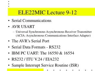
Introduction • Serial Decoder/Multiplexer • Allows a “Master” to communicate with multiple “Slaves” using fewer pins than dedicating a Port • Applications • Microcontroller-based systems • Consumer Products • Theory • Address and Data share signal at different times. • Decoder selects the receiving slave • Mux chooses the transmitting slave
Cost Analysis • Time spent on each phase of project • Verifying Logic: 4 weeks • Verifying timing: 1 long night • Layout: 2 long nights • Post-Extracted Timing: 2 long nights • LVS Success on First Run with No Errors: Priceless
Lessons Learned • Flip-Flops require special attention • Start Early • Work Together • Start Early • Routing is good fun
Summary • Our circuit is within spec. • Clock > 200MHz • 316 x 274 μm • 12.9mW @ 14.9 W/cm2 • Potential Improvements: • Stabilization D-Flip-Flops • Parity Check • Tri-state Buffer output
Acknowledgements • Thanks to Cadence Design Systems. • Thanks to Professor David Parent for his support. • Thanks to Morris Jones, for his State Machine intervention. • Thanks to Dr. T’s MIST Lab. • Thanks to the janitorial staff of SJSU. • Thanks to Coca-Cola and Gordon Biersch. • Thanks to Nick’s Pizza and the ghetto pizza place across from the Subway we used to go to before the one opened in the Student Union. • Thanks to Microsoft, Bungie, and Halo 2.
Tenacious EE Strikes Again