Creating 2D Sketch and Extruding Features in CAD Software for U-Bracket Design
In this assignment, you will learn how to create a 2D sketch and extrude features in CAD software to design a U-bracket. Start by making a new standard IPT file and turning on visibility. Create the base sketch on the XZ plane with rectangles and circles, applying dimensions and constraints. Follow the steps to finish the sketch and extrude features. Learn to utilize feature suppression to enhance design flexibility. This assignment builds foundational skills necessary for future projects.


Creating 2D Sketch and Extruding Features in CAD Software for U-Bracket Design
E N D
Presentation Transcript
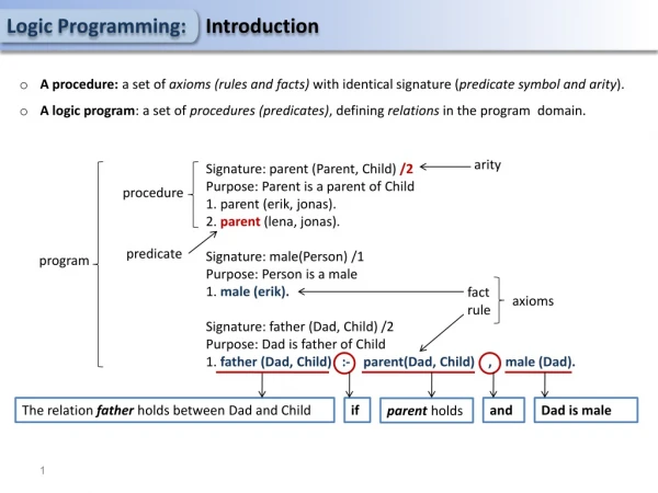
Parent Child Relationships Assignment D7
DO 1 • Make a new standard(IN).ipt file • Turn on visibility • Make a new sketch on the XZ Plane • You may need to flip your drawing over so that the top is the correct way arround.
DO 2 • Create the 2D Sketch for the base feature • Make a rectangle around the origin, but not centered on the origin.
DO 3 • Add the circles shown
DO 4 • Trim, as shown
DO 5 • Add dimensions and constraints shown, do not worry about the numbers display, we will fix those in the next step. Some of the constraints may already be there, that’s ok
DO 6 • You should be fully constrained at this point • Update the measurements to the ones shown
DO 7 • Finish the Sketch • Extrude it up .5 Inches
Create the 2nd Solid Feature • Notice that the Base of the feature is aligned to the center point. • We will create the sketch for this on the XY Workplane
DO 8 • We want to change the visual style so we can see ‘inside’ the base shape • If you press F7, you will see a cutaway view • Use the Center Point Arc tool and draw the arc shown. Click origin, then click the two outer points along base line
DO 10 • Draw a line across the bottom connecting the two outer points of the arc • Add the dimension 1.75 as shown on the last slide • Finish the sketch • Extrude it 2.5 symmetrically
DO 11 • Create a new sketch on the front face, • Add the rectangle shape, and dimensions as shown • Finish the Sketch
DO 12 • Extrude the sketch as a cutout • Save your work as D7.U-Bracket
Feature Suppression • We can turn features on and off • This gives us flexability to use one part for different designs • We are going to Supress the Square cutout and add a round cutout to the same file
DO 13 • Right click on the rectangular cutout, and click supress • It is still there, we just have it turned off
DO 14 • Create a new sketch, again on the front face • Draw the circle shown with a diameter of 2.5 • Extrude it through as before
DO 15 • As you can see, this make is easier to add flexibility to our designs. • Resave your file, we will need it for the D8 assignment next week • There are 3 exercises that go with this base assignment D7.ex1-D7.ex3