Download
1 / 46
460 likes | 677 Vues
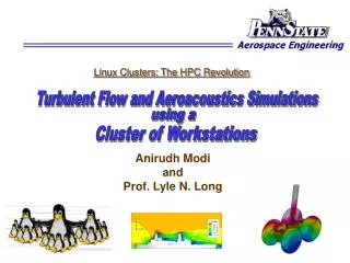
Final PhD Defense. Real-Time Visualization of Aerospace Simulations. using Computational Steering and Beowulf Clusters. Anirudh Modi 18 th July, 2002. Advised by: Prof. Lyle N. Long Prof. Paul E. Plassmann. OUTLINE. Motivation Introduction Computational Steering

E N D
Final PhD Defense Real-Time Visualization of Aerospace Simulations using Computational Steering and Beowulf Clusters Anirudh Modi 18th July, 2002 Advised by: Prof. Lyle N. Long Prof. Paul E. Plassmann
OUTLINE • Motivation • Introduction • Computational Steering • Wake-Vortex Simulations • CFD Simulations • Results & Performance • Conclusions • Questions/Suggestions?
Motivation • There has been a tremendous growth in speed and memory of parallel computers (+ Advent of cheap Beowulf clusters ). • Computational methods are getting increasingly important for simulating all kinds of physical phenomena, from simple to extremely complex. • Data from large parallel computations will not fit on graphics workstations anymore! • There is a growing need to be able to steer long running simulations and visualize their results as and when they are being computed. • Combining remote visualization with complex simulations in real-time gives us a powerful tool to tackle a new world of problems. • There have been major advances in programming languages and compilers (C++: Object-Oriented Programming).
Computational Steering • Running a complex program on a high-performance computing (HPC) system poses major difficulties in observing output. • Usually, simulation severely limits interaction with the program during the execution. • Makes visualization and monitoring very slow and cumbersome (if at all possible). • It the program is run remotely, additional difficulties arise. • How do we monitor (observe the output) and steer (change the input) for such a program in real-time?
Computational Steering • Software tools that support these activities are called computational steering environments. • They operate in three phases: • Instrumentation: Application code is modified to add monitoring functionality. • Monitoring: Program is run with some initial input data, the output of which is observed by retrieving important data about the program’s state change. • Steering: Program’s behavior is modified (by modifying the input) based on the knowledge gained during the previous phase by applying steering commands, which are injected on-line.
Previous Work • Several well-known computational steering systems exist: Falcon from Georgia Tech, VASE (Visualization and Application Steering) from UIC, SCIRun from Univ of Utah, CUMULVS from Oak Ridge National Lab, CSE (Computational Steering Environment) from Center of Mathematics and Computer Science in Amsterdam, Virtue from UIUC. Summary of characteristics of existing steering systems (Courtesy Reitinger)
Previous Work • Powerful, but complex systems with a steep learning curve. • Bulky. Difficult to setup and use. • Mainly aimed at computer scientists, not at computational scientists. • ALICE Memory Snooper from Argonne: • Good, lightweight (API similar to MPI). • Not object-oriented and therefore not very easy to use.
Computational Steering Library • POSSE:Portable Object-oriented Scientific Steering Environment • Written entirely in C++ using advanced features such as classes, templates, polymorphism. • Uses sockets for communication and pthreads for threading • A simple C++ class interface (DataServer/DataClient). • Extremely easy to use! (Hides most of the complexities involved in the process from the user). • Compact (3500 lines of code), Fast (extensive use of templates), Portable (has been tested on Linux/HP-UX/SunOS/Windows 2000 as of now), Multi-threaded (simultaneous multiple clients supported) and Lightweight(very low overhead).
Computational Steering POSSE
Computational Steering POSSE design
POSSE: Challenges • Challenges: • Byte ordering (endianness) among various architectures (Intel is little-endian, HP-UX/SunOS are big-endian). • Byte alignment problems. Structs are packed in different ways in different architectures (also by different compilers on the same OS) and therefore may not have the same size. This makes communication of one structure from one platform to the other difficult. • Handling user defined structures with ease. • Data Coherency
POSSE: Challenges • Byte ordering: • If client/server have same byte order, no problem! (no fixed network byte order used: for optimization). • Keep track of element size for all types of data (arrays, variables, etc) using templates and/or RTTI (slower). • User can choose who needs to do the conversion (can be either client or server depending on the application). • Byte alignment problems: • User has to define packStruct(myStruct *S, ...) and unpackStruct(myStruct *S,...) for packing/unpacking the array manually using POSSE supplied macros. • Can be automatically generated using lex/yacc/cpp (not yet implemented).
POSSE: Challenges • Data Coherency: • On server-side, use binary semaphores to lock/unlock read-write data (critical portion) when being modified. This has to be done by the user. • Modification on server-side is first-received in a buffer and then copied after the data is locked with the semaphore (speed). • Client can can either poll or use publish/subscribe methodology (future work).
Computational Steering Library • Server Side: • Functions for registration of data. • Initializing DataServer class. • Functions for locking data (if necessary) • Client Side: • Initializing DataClient class. • Calling send/recv functions. • Has support to pass user-defined structures very easily by defining functions packStruct() and unpackStruct().
Computational Steering Library #include "dataserver.h" int dummyInt = 0, n1, n2; double **dyn2D; REGISTER_DATA_BLOCK() { // Register global data REGISTER_VARIABLE("testvar", "rw", dummyInt); REGISTER_DYNAMIC_2D_ARRAY("dyn2D", "ro", dyn2D, n1, n2); } int main(int argc, char *argv[]) { DataServer server(4096); n1 = 30; n2 = 40; ALLOC2D(&dyn2D, n1, n2); for (int iter = 0; iter < MAX_ITER; iter++) { server.Wait("dyn2D"); // Lock DataServer access for dyn2D Compute(dyn2D); // Update dyn2D with new values server.Post("dyn2D"); // Unlock DataServer access for dyn2D } FREE2D(&dyn2D, n1, n2); } Example POSSE server code
Computational Steering Library #include "dataclient.h" int main(int argc, char *argv[]) { DataClient client(“cocoa.ihpca.psu.edu”, 4096); double **dyn2D; client.SendVariable("testvar", 100); // Send new value for "testvar" int n1 = client.getArrayDim("dyn2D", 1); int n2 = client.getArrayDim("dyn2D", 2); ALLOC2D(&dyn2D, n1, n2); client.RecvArray2D("dyn2D", dyn2D); Use(dyn2D); // Utilize dyn2D FREE2D(&dyn2D, n1, n2); } Example POSSE client code
POSSE: User-defined structs typedef struct { int i; double d; double a[200][400]; } Trajectory; int packStruct(Trajectory *T, unsigned char **dataptr, int &totsize) { totsize = sizeof(T->i) + sizeof(T->d) + sizeof(T->a); unsigned char *data = new unsigned char[totsize]; *dataptr = data; int ptr = 0; PACK_VARIABLE(T->i, data, &ptr); PACK_VARIABLE(T->d, data, &ptr); PACK_2D_ARRAY(T->a, data, &ptr); return ptr; } Packing of custom structure
POSSE: User-defined structs typedef struct { int i; double d; double a[200][400]; } Trajectory; int unpackStruct(Trajectory *T, unsigned char *data, int size) { int ptr = 0; UNPACK_VARIABLE(&(T->i), data, &ptr); UNPACK_VARIABLE(&(T->d), data, &ptr); UNPACK_2D_ARRAY(T->a, data, &ptr); return ptr; } Usage: Trajectory S; client->SendStruct(“keyword”, &S); client->RecvStruct(“keyword”, &S); Unpacking of custom structure
What is Wake-Vortex? • Moving aircraft generate wakes in the form of two counter-rotating swirling rolls of air, termed wake-vortex pair. • These wake-vortex pairs stretch for several miles behind the aircraft and last for several minutes. Their strength depends on the size, weight and speed of the aircraft, and the prevailing weather conditions. • They are mostly invisible, and can have a destabilizing effect on any aircraft encountering it. Note: These are not jet contrails!! Wake-vortex generated by a Boeing 727 (Courtesy NASA) Schematic of a wake-vortex pair
Why is Wake-Vortex Important? • NASA predicts that air-traffic will triple by 2022. If wake-vortex hazard avoidance systems do not improve significantly, there might be a major accident every week! • Wake-vortex hazard problem is major bottleneck for airport capacity, and a challenge for ATC. • Wake-vortex prediction for an entire fleet of aircraft taking-off and landing at a busy airport is an extremely computationally intensive problem.
Wake-Vortex Hazards • A commercial aircraft like a Boeing 737 can be thrown out of control if it follows too close behind a large aircraft such as a Boeing 747 (or even a smaller 727). • The infamous US Air Flight 427 (Boeing 737) disaster on September 8, 1997 is attributed to this phenomenon (following a Boeing 727). The recent Airbus crash in New York (Nov ’01) is also attributed to this phenomenon (although not confirmed). • Currently, empirical spacings (based on worst-case scenarios) are used to compensate for the lack of understanding of the strengths and positions of the vortices (e.g., a small aircraft should follow atleast 7 miles behind a heavy jet such as a Boeing 747). These cost the airline industry several billion dollars annually!
Problem Complexity • Example: Dallas/Fort Worth (DFW) airport (3rd busiest): 7 runways, handle nearly 2,300 take-offs and landings everyday! • For the wake-vortex code to track the vortices shed by an aircraft for 5 miles after take-off, assuming that a vortex code is tracked every 5 meters, 5x1600/5x2=3200 vortex filaments have to be tracked. • However, the wake-vortex simulation is an O(N2) problem (i.e., every vortex element is influenced by all the other vortex elements). Even if the induced velocity effect due to vortices from other aircraft are ignored: 3200^2=10.24 Million computations/airplane/timestep. • For 2300 planes/day: 10.24x2300/24/2 = 0.5 Billion calc/timestep!! • Each induced-velocity computation is 200-300 flops! Hence, 100-150 GFlop/timestep!! • However, with some assumptions (shown in pseudocode ahead) and state-of-the-art computing hardware, we can carry these calculations in near real-time (i.e, we can simulate say, 10 min of wake-vortex physics in 10 min of physical clock time).
Previous Work: AVOSS • NASA researchers have designed a system to predict wake-vortices: Aircraft VOrtex Spacing System (AVOSS). • AVOSS determines how winds and other atmospheric conditions affect the wake-vortex patterns of different types of aircraft. • It integrates the output from a number of subsystems: weather, wake prediction, wake sensors. Being tested at Dallas/F-W airport since 1997. • Although AVOSS carries out a rigorous simulation of wake-vortices, it does not implement any system for their visualization. • Hence, it is unable to provide information like alternate trajectories for the take-off and landing of aircraft, etc.
Simulation Pseudocode Reduces complexity by a factor of N/4k
Simulation Modules • Parallel Computing (Vortex-Wake code/CFD code) • Beowulf Clusters • MPI • Real-time Monitoring and Steering • C++ Computational Steering Library • Virtual Reality • CAVELib on RAVE
Wake-Vortex Simulation • Code is parallelized using MPI to track vortex elements from each plane on a different processor (simple scheduling), so that we get an almost real-time solution with tolerable lag (Dt). • Aircraft keep entering and leaving the airport => data-structure in the wake-vortex program should be able to handle this. Hence, STL vector is used for the aircraft data-structure, which adds an aircraft in constant time, and deletes in linear time. • Special data-structure has to be maintained for wake-vortices, as they remain even after the aircraft has left the domain of interest.
Wake-Vortex Hazard Simulation • The weather condition and location for each aircraft are randomly generated by the Airport Data Server. In practice, this will come from the GPS on the aircraft and weather sensors at the airport. • The VR application will be written in C++ using OpenGL and GLUT (openGL Utility Library) on top of CAVELib. • A simple noise prediction code (based on empirical data) is also run from within the visualization client to generate the noise levels around the plane due to its engines. The dB value from the client is then sent to the Bergen Sound Server to be output by a set of speakers.
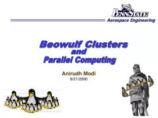
Beowulf Clusters • Multi-computer architecture which can be used for parallel computations. • Uses commodity personal computers, standard network adaptors and switches. • Does not contain any custom hardware components and is trivially reproducible. Extremely cost-effective! • Using commodity (and usually public domain) software like the Linux OS, MPI, and other widely available open-source software. • First Beowulf cluster was built by NASA in 1994 (consisted of 16 486DX4-100 MHz machines).
Beowulf Clusters • IHPCA has its own clusters: COCOA (COst effective COmputing Array) and COCOA-2. • COCOA: 50-proc PII-400 cluster with 12.5 GB RAM, fast ethernet • COCOA-2: 40-proc PIII-800 cluster with 20 GB RAM, dual fast ethernet COCOA ($100K in 1998) COCOA-2 ($48K in 2000)
Visualization Hardware • RAVE: Reconfigurable Automatic Virtual Environment • A popular and sophisticated VR installation similar to the CAVE (with just 1 screen). • It is projection-based system that surrounds the viewer with 1 or more screens and supports stereo display using shutter glasses, and electro-magnetic tracking equipment with a wand for interaction. CAVE/RAVE schematic Snap of the IHPCA RAVE
VR Software • VR hardware devices are very complex. • Specialized Application Programming Interfaces (APIs) are essential to make the development of VR applications easier. • CAVELib is an API that provides general support for building virtual environments for various types of immersive displays. • It was originally developed by Dave Pape of EVL, UIC, and is now marketed commercially by VRCO.
CAVELib • CAVELib configures the display device, synchronizes processes, draws stereoscopic views, creates a viewer-centered perspective and provides basic networking between remote VEs. • Provides standardization: Allows single program to be available on a wide variety of display devices. • It uses threads to obtain simple parallelization in the calculation process by using by using one process for projection on each wall. • VRJuggler is another C++ API similar to CAVELib (C). Unlike CAVELib, VRJuggler is public domain software, developed and maintained by Iowa State University.
OpenGL • CAVELib by itself does not incorporate functions for the actual graphics programming (display). OpenGL API is used for that. • OpenGL is an industry standard for graphics programming and is thus portable across platforms • With the combination of OpenGL and CAVELib, powerful VR applications can be created. • OpenGL is enhanced by the use of additional utility libraries like GLUT and GLX.
Final Visualization A Screenshot of the Vortex Visualization program
CFD Simulations: PUMA2 • Parallel Unstructured Maritime Aerodynamics, PUMA, originally written by Dr. Christopher W.S. Bruner. • Modified extensively and re-organized for efficient performance on Beowulf Clusters [PUMA2]. • 3-D Euler/Navier-Stokes solver. • Written entirely in ANSI C using MPI library. • Based on Finite Volume method. • Supports mixed topology unstructured grids composed of tetrahedral, wedges, pyramids and hexahedral (bricks) • Preserve time accuracy or pseudo-unsteady formulation. • Uses dynamic memory allocation. • Runge-Kutta, Jacobi and various Successive Over-relaxation Schemes (SOR), as well as both Roe and Van Leer numerical flux schemes
Modifications to PUMA2 • The POSSE server component, DataServerMPI, was added to the main() function of PUMA2. • This was done by registering the cell-centered flow vector [r , u, v, w, p] and various important flow parameters in the code (Grid and flow properties, CFL number, flux scheme, integration scheme, etc). • Several new global variables were added and registered to receive iso-surface requests and store resulting iso-surfaces. • An iso-surface extraction routine (based on the marching-tetrahedra algorithm) was added to PUMA2. • Since this implementation expects the flow data at the nodes of every tetrahedron, a subroutine to interpolate the flow data from cell-centers to the nodes also had to be added to PUMA2.
Graphical User Interface Screenshot of PUMA GUI with VTK window Screenshot of PUMA GUI with Tecplot integration feature
Visualization Snapshots 1.3 M cells, 1.8 GB memory (16 nodes on COCOA-2) 0.8 M cells, 1.8 GB memory (16 nodes on COCOA-2) Visualization using the Tecplot integration feature of the POSSE GUI
Scalability and Dimensional Reduction • For an evenly distributed grid, the number of grid points on each processor of a parallel computation is N/P where N is the total number of grid faces and P is the total number of processors. • Scalability: Computational time for extraction of an iso-surface is O(N/P) as compared to the sequential algorithm which takes O(N) for the same procedure. • Dimensional Reduction: Data required for the CFD simulation lives in higher dimensional space (3-D) than the data that is required for visualization (which are in 2-D and 1-D space for iso-surfaces and chord plots, respectively) => O(N2/3) • Combined effect:O(N2/3/P) • Computation is perfectly scalable O(N/P). Less network bandwidth is required due to only O(N2/3) data traveling between the client and the server.
Dimensional Reduction Percentage of Mach and Cp iso-surface triangles for the Apache Helicopter case
POSSE Performance Single client performance Multiple client performance
POSSE Performance SMP performance (for server-side program)
Conclusions • POSSE has proven to be a very powerful, yet easy to use software with a high rate of acceptance and approval in our research Group. If scientists are given an easy to use software system with a mild learning curve,they will use it. • It enables us to carry out and debug complex simulations in real-time with considerable ease using a client-server architecture. • It opens a new way for the ATC to effectively deal with the wake-vortex hazard problem and to improve the capacity and safety of large airports. • The coupling of computational steering to our parallel simulation makes the real-time visualization of the CFD simulations possible. Scalability and dimensional reduction arising from this approach make the implementation efficient. • At a more basic level, this ability to interact and visualize a complex solution as it unfolds and the real-time nature of the computational steering system opens a whole new dimension to the scientists for interacting with their simulations.
Webpage: http://posse.sourceforge.net/ http://www.anirudh.net/phd/ http://www.personal.psu.edu/lnl/ Questions?