Download
1 / 15
180 likes | 621 Vues
A Higher-Mode Annular-Ring Patch Antenna With a Photonic-Bandgap Ground Plane. Shun-Yun Lin Department of Electrical Engineering Cheng Shiu Institute of Technology Kaohsiung, Taiwan Email: linsy@ema.ee.nsysu.edu.tw Kin-Lu Wong Department of Electrical Engineering

E N D
A Higher-Mode Annular-Ring Patch Antenna With a Photonic-Bandgap Ground Plane Shun-Yun Lin Department of Electrical Engineering Cheng Shiu Institute of Technology Kaohsiung, Taiwan Email: linsy@ema.ee.nsysu.edu.tw Kin-Lu Wong Department of Electrical Engineering National Sun Yat-Sen University Kaohsiung, Taiwan Email: wongkl@ema.ee.nsysu.edu.tw
OUTLINE • INTRODUCTION • Annular-ring patch antenna operated at TM21 mode • Patch antenna with a PBG ground plane • ANTENNA DESIGNS • EXPERIMENTAL RESULTS • CONCLUSIONS
INTRODUCTION-1 • The resonant frequency of TMnm mode can be calculated by the mode chart • As w/R is increased, the value of kR becomes less than n for a given mode • When the ring width reach half the guided wavelength, higher order TMnm(n0, m>1) appear. 2w R
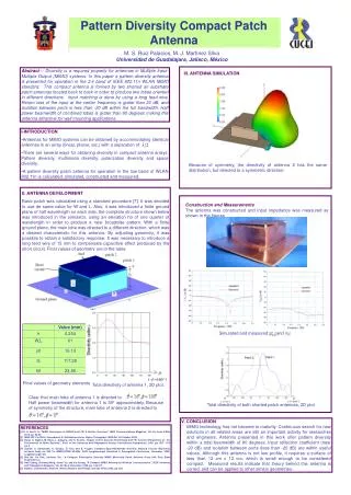
INTRODUCTION-2 • The typical radiation has a peak value at about 35° away from broadside direction • Both horizontal and vertical planes have conical radiation patterns • The radiated power in azimuth plane is non-uniform
INTRODUCTION-3 Patch antenna with slotted ground plane Compact LP antenna Compact DP antenna Compact CP antenna
Patch antenna with Photonic BandGap ground plane PBG structure is a periodic structure The forbidden bands are characterized by period of structure shape of the individual element of the lattice size of the individual element of the lattice Applied to antenna design isolation enhancement harmonic control gain enhancement impedance bandwidth enhancement INTRODUCTION-4
ANTENNA DESIGN-1 PBG ground plane • A square lattice of 3 x 3 circular slots are embedded • The ratio of the slot radius to the PBG period is selected to be 0.25 to obtain optimum stopband depth and passband ripples • The center frequency f0 of the stopbandis determined from f0 = c/2S
ANTENNA DESIGN-2 Slotted ground plane • Four circular slots are embedded in ground plane – have the same radius and spacing as those embedded in the PBG ground plane – placed in perpendicular to the surface current path of TM21 mode –located almost under the annular-ring radiating patch
EXPERIMENTAL RESULTS-1 Antenna with slotted ground plane Antenna with PBG ground plane Antenna with regular ground plane
The resonant frequency of the antenna with a slotted ground plane was greatly lowered The resonant frequency of the antenna with a PBG ground plane was slightly increased The impedance bandwidth for both antennas with the slotted and PBG ground planes are larger than the reference antenna EXPERIMENTAL RESULTS-2
Good conical radiation patterns are observed for three studied antenna, especially for the antenna with PBG ground plane The radiation patterns of the antenna with slotted ground plane has smaller beamwidth EXPERIMENTAL RESULTS-3 (a) Ref. Antenna at 2380 MHz (b)Antenna with slotted GND at 1920 MHz (c) Antenna with PBG GND at 2460 MHz
EXPERIMENTAL RESULTS-4 • The studied antenna with slotted ground plane has a patch size reduction of about 35% • The studied antenna with PBG ground plane has a large F/B ratio of 12.1 dB
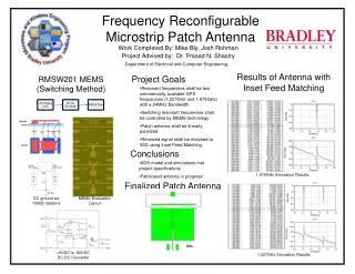
EXPERIMENTAL RESULTS-5 • The antenna with a slotted ground plane has the largest peak antenna gain • The gain variations of the antenna with a PBG ground plane is less than 0.5 dBi Ref. antenna Antenna with slotted GND Antenna with PBG GND
CONCLUSIONS • Annular-ring patch antenna with a slotted ground plane • Patch size reduced • Impedance bandwidth enhanced • Backward radiation increased • Annular-ring patch antenna with a PBG ground plane • Impedance bandwidth enhanced • F/B ratio enhanced • Small gain variations within the impedance bandwidth