Download
1 / 23
230 likes | 414 Vues
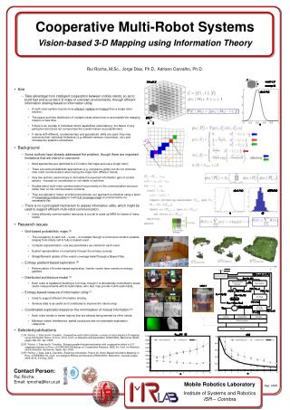
Measuring Cooperative Robotic Systems Using Simulation-Based Virtual Environment Xiaolin Hu Computer Science Department Georgia State University, Atlanta GA, USA 30303 Bernard P. Zeigler Arizona Center for Integrative Modeling and Simulation University of Arizona, Tucson AZ, USA 85721.

E N D
Measuring Cooperative Robotic Systems Using Simulation-Based Virtual Environment Xiaolin Hu Computer Science Department Georgia State University, Atlanta GA, USA 30303 Bernard P. Zeigler Arizona Center for Integrative Modeling and Simulation University of Arizona, Tucson AZ, USA 85721
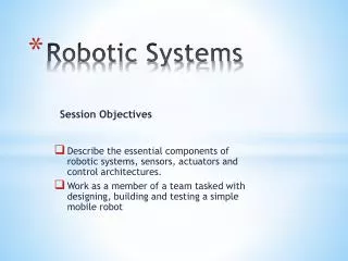
Agenda • Background on DEVS and Model Continuity • The Virtual Measuring Environment • The Robotic Convoy Example • Preliminary Simulation Results • Future Work
Derived from mathematical dynamical system theory Based on a formal M&S framework Supports hierarchical model construction Atomic model Coupled model Explicit time modeling real DEVS (Discrete Event System Specification)
The control logic to be designed Control model Control model Sensor/actuator Virtual Sensor/actuator Sensor/actuator interface Real environment Environment model Real environment Simulation & Test System in Execution Robotic system to be Designed Mapping Modeling A Background on Model Continuity for Robotic Software Development
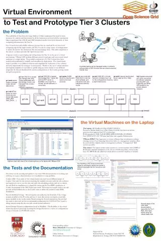
A virtual measuring environment – an intermediate step that allows models and real robots to work together within a “virtual environment” A Virtual Measuring Environment Simulation-based measuring using robot models and the environment model Real system measuring with all real robots within a real physical environment This virtual measuring environment will bring simulation-based study one step closer to the reality.
Realization of the Virtual Measuring Environment • Model Continuity allows the same control models used in simulation to be deployed to real robots for execution. The couplings among these models are maintained from simulation to execution. • The clear separation between the control model and sensor/actuator interface make it possible for the control model to interact with different types of sensors/actuators, as long as the interface functions between them are maintained. • The control model of a real robot can use real sensors/actuators to interact with the real environment and virtual sensor/actuators to interact with a virtual environment. • A real robot can communicate with robot models simulated on computers, resulting in a system with combined real and virtual robots.
virtual sensors HIL actuators virtual obstacle Control Model virtual counterpart of the real robot virtual robots wireless communication mobile robot Architecture of the Virtual Measuring Environment virtual environment computer
Robot Model Robot Model Robot Model Real Robot Real Robot Real Robot Virtual Sensor Virtual Actuator Virtual Sensor Virtual Actuator Virtual Sensor Virtual Actuator Virtual Sensor HIL Actuator Real Sensor Real Actuator Real Sensor Real Actuator Virtual Environment Virtual Environment Real Environment (a) (b) (c) Conventional simulation Robot-in-the-loop simulation Real system measurement An Incremental Measuring Process
Experimental Frames • input stimuli: specification of the class of admissible input time-dependent stimuli. This is the class from which individual samples will be drawn and injected into the model or system under test for particular experiments. • control: specification of the conditions under which the model or system will be initialized, continued under examination, and terminated. • metrics: specification of the data summarization functions and the measures to be employed to provide quantitative or qualitative measures of the input/output behavior of the model. Examples of such metrics are performance indices, goodness-of-fit criteria, and error accuracy bound. • analysis: specification of means by which the results of data collection in the frame will be analyzed to arrive at final conclusions. The data collected in a frame consists of pairs of input/output time functions.
An Architecture with Experimental Frames Control model of robots Define input stimuli, control, metrics, analysis from the measuring point of view Robot Models Experimental Frames Models of sensors and actuators Environment Model Model how the environment reacts/interacts with robots
…… BReadyIn FReadyOut Robotn Robot2 FReadyIn FReadyOut FReadyIn BReadyOut BReadyIn FReadyOut Robot3 FReadyIn BReadyOut Robot1 BReadyOut BReadyIn A Robot Convoy Example • Robots are in a line formation with each robot has a front neighbor and a back neighbor. • The system try to maintain the coherence of the line formation • A robot’s movements are synchronized with its neighbors • A robot (except the leader robot) goes through a basic “turn – move – adjust – inform” routine. • No global communication/coordination exists.
Robot Model FReadyIn FReadyIn FReadyOut FReadyOut Convoy BReadyIn BReadyIn BReadyOut BReadyOut moveComplete move Avoid move moveComplete HWInterface activity • Based on Brooks’ Subsumption Architecture • The Avoid model controls a robot to move away if the robot collides with anything. The Convoy model is fully responsible to control a robot to convoy in the team. • HWInterface activity is responsible for the sensor/actuator hardware interfaces.
D i i-1 di Ri-1 Ri i-1 i Ri-1 Ri i di-1 a Formula of Movement
TimeManagerN TimeManager1 RobotN tN Robot1 t1 SpaceManager moveComplete1 sensorData1 move1 startMove …… Robot1 (x, y) RobotN (x, y) Obstacles (x, y) …… …… …… …… sensorDataN moveCompleteN moveN startMove Environment Model • This TimeManager determines how long it takes for a robot to finish a movement. • The SpaceManager is a model of the experimental floor space, including the size, shape and position of the work area, the static objects and robots. • In this example we have ignored the detailed dynamic processes of a movement.
a D d Two Noise Factors Random numbers are used to simulate the noises and variances in robots’ movement. Distance noise factor (DNF): the ratio of the maximum distance variance as compared to the robot’s moving distance. Angle noise factor (ANF): the ratio of the maximum angle variance as compared to the robot’s moving distance.
Formation Coherence The formation coherence is affected by the noise factors. We use the average position error of the robot team as the indicator for the convoy system’s formation coherence: the smaller the error is, the more coherent the convoy system is. The position error does not accumulate over time – coherent.
Noise Sensitivity The system is insensitive to the noise factors as long as these factors are within a safe boundary. Series 1: DNF = 0.04, ANF = 0.04, average = 35.08 Series 2: DNF = 0.1, ANF = 0.08, average = 35.69 Series 3: DNF = 0.2, ANF = 0.1, average = 36.61
Scalability • It shows that the average position error increases as the number of robot increases. • If this trend holds true with more robots, the system is not scalable in the sense that it will eventually break as more robots are added into the system.
Environment Model …… …… Robot_1 Robot_k Robot_n Real environment abstract sensors – HIL motor real sensors – HIL motor abstract sensors – abstract motor A Future Experimental Setup For example, we can check the back robot’s position errors based on the position and direction of its front robot in the physical environment.