Download
1 / 23
240 likes | 503 Vues
EECS 318 CAD Computer Aided Design. LECTURE 2: The VHDL Adder. Instructor: Francis G. Wolff wolff@eecs.cwru.edu Case Western Reserve University. SoC: System on a chip (beyond Processor). The 2001 prediction: SoC’s will be > 12M gates. ASIC and SoC Design flow. Modelling types.

E N D
EECS 318 CADComputer Aided Design LECTURE 2: The VHDL Adder Instructor: Francis G. Wolff wolff@eecs.cwru.edu Case Western Reserve University CWRU EECS 318
SoC: System on a chip (beyond Processor) • The 2001 prediction: SoC’s will be > 12M gates CWRU EECS 318
ASIC and SoC Design flow CWRU EECS 318
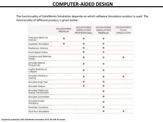
Modelling types • Behavioral model • Explicit definition of mathematical relationship between input and output • No implementation information • It can exist at multiple levels of abstraction • Dataflow, procedural, state machines, … • Structural model • A representation of a system in terms of interconnections (netlist) of a set of defined component • Components can be described structurally or behaviorally CWRU EECS 318
Adder: behavior, netlist, transistor, layout Structural model Behavioral model CWRU EECS 318
Full Adder: alternative structural models Are the behavioral models the same? CWRU EECS 318
Why VHDL? • The Complexity and Size of Digital Systems leads to • Breadboards and prototypes which are too costly • Software and hardware interactions which are difficult to analyze without prototypes or simulations • Difficulty in communicating accurate design information • Want to be able to target design to a new technology while using same descriptions or reuse parts of design (IP) CWRU EECS 318
Half Adder • A Half-adder is a Combinatorial circuit that performs the arithmetic sum of two bits. • It consists of two inputs (x, y) and two outputs (Sum, Carry) as shown. XYCarry Sum0 0 0 00 1 0 11 0 0 11 1 1 0 Carry <= X AND Y; Sum <= X XOR Y; Behavioral Truth Table CWRU EECS 318
Half Adder: behavioral properties What are the behavioral properties of the half-adder ciruit? • Event property The event on a, from 1 to 0, changes the output • Propagation delay property The output changes after 5ns propagation delay • Concurrency property: Both XOR & AND gates compute new output values concurrently when an input changes state CWRU EECS 318
Half Adder: Design Entity • Design entity A component of a system whose behavior is to be described and simulated • Components to the description • entity declaration The interface to the design There can only be one interface declared • architecture construct The internal behavior or structure of the design There can be many different architectures • configuration bind a component instance to an entity-architecture pair CWRU EECS 318
Half Adder: Entity a Sum b Carry ENTITY half_adder IS PORT (a, b: IN std_logic;sum, carry: OUT std_logic );END half_adder; • All keyword in capitals by convention • VHDL is case insensitive for keywords as well as variables • The semicolon is a statement separator not a terminator • std_logic is data type which denotes a logic bit (U, X, 0, 1, Z, W, L, H, -) • BIT could be used instead of std_logic but it is only (0, 1) CWRU EECS 318
Half Adder: Architecture ENTITY half_adder IS PORT (a, b: IN std_logic;Sum, Carry: OUT std_logic );END half_adder; must refer to entity name ARCHITECTURE half_adder_arch_1 OF half_adder IS BEGIN Sum <= a XOR b; Carry <= a AND b; END half_adder_arch_1; CWRU EECS 318
Half Adder: Architecture with Delay ENTITY half_adder IS PORT (a, b: IN std_logic;Sum, Carry: OUT std_logic );END half_adder; ARCHITECTURE half_adder_arch_2 OF half_adder IS BEGIN Sum <= ( a XOR b )after 5 ns; Carry <= ( a AND b )after 5 ns; END half_adder_arch_2; CWRU EECS 318
Full Adder: Architecture ENTITY full_adder IS PORT (x, y, z: IN std_logic;Sum, Carry: OUT std_logic );END full_adder; ARCHITECTURE full_adder_arch_1 OF full_adder IS BEGIN Sum <= ( ( x XOR y )XOR z ); Carry <= (( x AND y ) OR (z AND (x AND y))); END full_adder_arch_1; CWRU EECS 318
Full Adder: Architecture with Delay ARCHITECTURE full_adder_arch_2 OF full_adder IS SIGNAL S1, S2, S3: std_logic;BEGINs1 <= ( a XOR b ) after 15 ns;s2 <= ( c_in AND s1 ) after 5 ns;s3 <= ( a AND b ) after 5 ns;Sum <= ( s1 XOR c_in ) after 15 ns;Carry <= ( s2 OR s3 ) after 5 ns;END full_adder_arch_2; CWRU EECS 318
SIGNAL: Scheduled Event • SIGNAL Like variables in a programming language such as C, signals can be assigned values, e.g. 0, 1 • However, SIGNALs also have an associated time value A signal receives a value at a specific point in time and retains that value until it receives a new value at a future point in time (i.e. scheduled event) • The waveform of the signal is a sequence of values assigned to a signal over time • For example wave <= ‘0’, ‘1’ after 10 ns, ‘0’ after 15 ns, ‘1’ after 25 ns; CWRU EECS 318
Hierarchical design: 2 bit adder LIBRARY IEEE; USE IEEE.std_logic_1164.ALL; ENTITY adder_bits_2 IS PORT ( Carry_In: IN std_logic;a1, b1, a2, b2: IN std_logic; Sum1, Sum2: OUT std_logic;Carry_Out: OUT std_logic ) END adder_bits_2; • The design interface to a two bit adder is • Note: that the ports are positional dependant (Carry_In, a1, b1, a2, b2, Sum1, Sum2, Carry_out) CWRU EECS 318
Hierarchical designs: Ripple Structural Model ARCHITECTURE ripple_2_arch OF adder_bits_2 IS COMPONENT full_adder PORT (x, y, z: IN std_logic; Sum, Carry: OUT std_logic); END COMPONENT; SIGNAL c1: std_logic; BEGINFA1: full_adder PORT MAP (Carry_in, a1, b1, Sum1, c1); FA2: full_adder PORT MAP (c1, a2, b2, Sum2, Carry_Out); END ripple_2_arch; CWRU EECS 318
Assignment #1 (1) Using the full_adder_arch_2, a <= ‘1’, ‘0’ after 20 ns; b <= ‘0’, ‘1’ after 10 ns, ‘0’ after 15 ns, ‘1’ after 25 ns; c_in <= ‘0’, ‘1’ after 10 ns;Hand draw the signal waveforms for a, b, c_in, s1, s2, s3, sum, c_out (2) Write the entity and architecture for the full subtractor (3) Write the entity and architecture for a 4 bit subtractor Note: this is a hand written assignment, no programming.Although, you may want to type it in using a Word Processor. CWRU EECS 318