Wireless Power Transmission
Wireless Power Transmission. Resonating into the Future Tony Xiao, Chris Jereza, Javier Pinedo Advisor: Dr. Sakhrat Khizroev Winter/Spring 2008. Concept and Application. Intended as a proof-of-concept for remotely powered electrical devices Uses RF Transmitter and Receiver

Wireless Power Transmission
E N D
Presentation Transcript
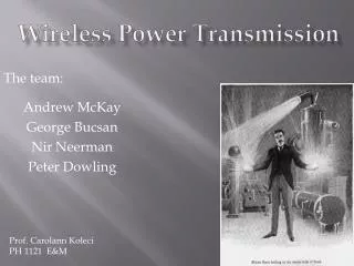
Wireless Power Transmission Resonating into the Future Tony Xiao, Chris Jereza, Javier Pinedo Advisor: Dr. Sakhrat Khizroev Winter/Spring 2008
Concept and Application • Intended as a proof-of-concept for remotely powered electrical devices • Uses RF Transmitter and Receiver • Operates using Ferromagnetic Resonance (FMR) • Boasts many advantages over alternate implementations of wireless power. • Many times the range of inductive charge platforms, mechanically simpler than evanescent wave coupling, safer than direct transmission. • Has great potential for future applications • Over $2 Billion USD Projected Annual Earnings (from PowerCast Estimate)
Ferromagnetic Resonance • Ferromagnetic Materials such as Iron, Nickel and Cobalt have aligned magnetic dipole moments • Flipping of electrons from high and low moments absorbs EM energy when in an external magnetic field • Far more powerful than NMR (3000 times)
Technical design objectives • Primary Goal: Detect notable power absorption in a FM sample • At least 10-20 dBm power absorption • Sufficient SNR for practical detection • Frequency of RF: 0.5 to 3.0 GHz • Cutoff Frequency: Under 100 khz • Magnetic Field Strength: Under 1 Tesla (10,000 Gauss)
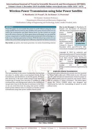
Test Assembly High Level Design Coil Center Voltmeter Voltmeter Detector Coil Region Ferromagnetic Sample Core Sample Center Thermocouple Source Coil Region Sample Offset Current Source Spectrum Analyzer Signal Generator Spectrum Analyzer Reference Signal
Noise-Elimination Connector Modified N-type Connector for noise elimination: Over 90% decreased noise compared to direct connection Grounding Line RG-8/u Coaxial Cable Connection to Test Assembly Faraday Caging N-type (Male) connector Modified N-type (Female) connector
Technical challenges • Accurately modeling/predicting FMR • Determining ideal test assembly specifications, resonance parameters. • Eliminating Noise in Transmission Line • Adequately shielding main test assembly • Designing compatible low-noise connector for assembly and cables • Eliminating the need for resonant cavity
Project Roles • Tony Xiao: • Theoretical High-Level Design • Manager and Inter-university Liaison • System Testing and Analysis • Chris Jereza: • RF Connector Design, Construction • Interference Reduction Design • Component Procurement • Javier Pinedo: • Test Assembly Construction and Calibration • Webmaster and Documentation • System Testing
Design Considerations and Future Experiments • This was a Proof of Concept • Cost is relatively low per-unit • Implementing a voltage converter • Implementing Advanced Detection Methods: Giant/Tunneling Magnetoresistive elements • Testing more Materials: Permalloy, Samarium-Nickel Alloys. • Feasibility studies for system Nanoscaling
Test Results • Peak absorption resonance detected at Freq: 1064MHz • Absorption: Approx from -34 to -47 dbm. (398nw -> 20nw. 3780nw absorbed). Approx 95% efficiency. • Estimated SNR: Approx 2.51 x 10^10 • Peak absorption at 3800 Gauss external field • Optimal test assembly coil specifications: 70 turn end regions, 57 turn detection region, with 10.76mm diameter. • Material: Magnetic Iron, 10mm Diameter
Baseline Readings • No External Field Iron Sample • Non-Magnetic Sample Baseline
Baseline Readings • 3800 Gauss External Field Iron Sample • 5000 Gauss External Field Iron Sample
Data Analysis • 5000 Gauss Vs No Field • 3800 Gauss Vs No Field
Data Analysis • Area of interest, 3800 Gauss • Maximum absorption at 1064 MHz • Approx from -34 to -47 dbm. (398nw -> 20nw. 3780nw absorbed). • Matches precisely with calculation: f = (У/2π)*β • У = 1.758 * 10^10 (1/s*T) (Gyromagnetic Ratio of Iron) • B = 3800 Gauss = 0.38T (Field) • Result: f = 1063.2mHz
Summary • Achieved excellent results with a simple test assembly, further strengthening results • Confirmed 95% absorption at 1065 mHz and optimal conditions in agreement with theory • Verified feasibility of overall system scheme • Potential for continuing study with more advanced detection and conversion methods • A successful test of a new approach to an emergent technology field