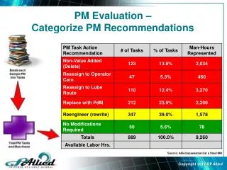
PM-DCAS
The Post-Moog Digitally Controlled Analog Synthesizer. Group Members. PM-DCAS. Robert Estelle Toan Ho Greg Hartl Logan Snow. Project Summary. What: Digitally Controlled Analog Synthesizer Why: Flexibility of digital control Recreate classic analog sounds Who: Hobbyist musicians


PM-DCAS
E N D
Presentation Transcript
The Post-Moog Digitally Controlled Analog Synthesizer Group Members PM-DCAS • Robert Estelle • Toan Ho • Greg Hartl • Logan Snow
Project Summary • What: • Digitally Controlled Analog Synthesizer • Why: • Flexibility of digital control • Recreate classic analog sounds • Who: • Hobbyist musicians • Synth enthusiasts • Cost: • Low-cost digital and analog components • Totaling less than $200
Technical Objectives • Synthesize traditional analog sounds • Use modular analog components • Support MIDI input • Store and recall presets • Maintain a low cost
Analog Signal Flow MIDI Microcontroller VCO VCF VCA1 Noise VCA2 Output
VCO – Voltage Controlled Oscillator MIDI Microcontroller I’m a big picture of the VCO VCO VCO VCF VCA1 • 1V/Octave control input • At least 3 Octave range • Several Outputs: • Sine wave • Sawtooth wave • Rectangular wave with PWM • Triangular wave • Outputs are mixed before entering VCF Noise VCA2 Output
Noise Source MIDI Microcontroller I’m a big picture of the noise source • White noise • Adjusted through VCA2 before mixing with VCO signals VCO VCF VCA1 Noise Noise VCA2 Output
VCF – Voltage Controlled Filter MIDI Microcontroller • Voltage-controlled resonance and center frequency • Multiple Filter Outputs • High Pass • Low Pass • Band Pass VCO VCF VCF VCA1 I’m a big picture of the VCF Noise VCA2 Output
VCA – Voltage Controlled Amplifier • Logarithmic control voltage • Single board with two amplifiers • VCA1 is dedicated to filter output • VCA2 is dedicated to noise source • VCA1 output connects to final synthesizer output MIDI Microcontroller VCO VCF VCA1 VCA1 I’m a big picture of the VCA Noise VCA2 Output
User Interface Board Objectives • Intuitive interface • Analog feel • Digital control • Interface must be readable by microcontroller • Interface must be writable by microcontroller (in order to support preset recall)
Digital Rotary Knobs • Digital rotary encoder read by the microcontroller • LEDs indicate position of knob to user • Display can be reset by microcontroller to indicate new position
User Interface Design Attack Decay Sustain Release • Noise • Sine • Saw • Tri • Rect Pulse Width Vibrato Center Volume Resonance Options Filter Mode Modulation Variance Filter LPF HPF Fixed Tri BPF Sine P1 P2 P3 P4 Save
Digital Control Scheme … … LED Driver LED Driver … MIDI Keyboard Microcontroller I2C DAC I2C DAC … VCO Control Filter Resonance Other Control Voltages
Demonstration • Demonstration Requirements • Will support adjustment of audio parameters • Will support saving and loading of presets • Will support MIDI input and produce audio output Basically – we will play some groovy music for the class!
Testing and Development • Analog Component Level Testing • LabView to generate analog test signals • Oscilloscopes to verify waveform properties • Circuit tuning and analysis by ear • Digital System Testing • Logic analyzer for synchronizing digital signals • Serial connection for debug output • Internal status LEDs
Problems or Issues • Analog boards are built but untested • Control board layout not complete • Part inventory is incomplete
Remaining Tasks • (24 Oct.) Complete control board layout • (27 Oct.) Test each analog component board • (31 Oct.) Acquire control board components • (Nov.) Construct control interface board • (Nov.) Program microcontrollers • (1 Dec.) Design and construct enclosure
Project Status • Nearly all parts have been received • Voltage controlled boards have been constructed (VCO, VCF, VCA, and noise source) • User interface board has been laid out • Working on laying out digital control board and developing microcontroller software