Download
1 / 13
140 likes | 730 Vues
Update on “Channel Models for 60 GHz WLAN Systems” Document. Date: 2009-07-15. Authors:. Abstract. This presentation describes changes in the document “Channel models for 60 GHz WLAN systems,” (IEEE 802.11-09/0334) made from r 2 ( May 2009) to r3 (July 2009). Summary of Updates.

E N D
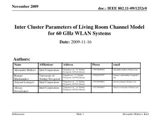
Update on “Channel Models for 60 GHz WLAN Systems” Document Date: 2009-07-15 Authors: Alexander Maltsev, Intel
Abstract • This presentation describes changes in the document “Channel models for 60 GHz WLAN systems,” (IEEE 802.11-09/0334) made from r2 (May 2009) to r3 (July 2009). Alexander Maltsev, Intel
Summary of Updates • Two main updates were done in the r3 version of the “Channel models for 60 GHz WLAN systems” document relatively to the r2 version: • Polarization impact modeling (new Sections 2.4, 3.4, 3.6). • Conference room channel model for simulation of links between a STA on the table and the AP (new Sections 3.5, 3.6) • Other sections of the document updated to include these new features. Alexander Maltsev, Intel
Polarization Impact Modeling (1 of 3) It was demonstrated in [2], [3] that polarization impact is very strong for 60 GHz WLAN systems and that a mismatch in polarization characteristics of the transmit and receive antennas can result in a degradation of the received power by 10-20 dB. Support of polarization characteristics is included as one of the requirements for the TGad channel model [4] Polarization characteristics impact has to be accurately predicted for different signal propagation paths and for antennas with different types of polarization (linear, circular, adaptive polarization). Alexander Maltsev, Intel
Polarization Impact Modeling (2 of 3) The methodology for polarization impact modeling was proposed in [5]. This approach was applied to the conference room channel model. The used methodology allows to account for cross-polarization coupling because of the geometrical depolarization and due to cross-polarization coupling at the reflections. Polarization impact was modeled at the cluster level and all rays within one cluster were assumed to have the same polarization characteristics. In the developed channel model, channel clusters correspond to different first and second order reflected signal paths. The polarization does not change at the free space propagation but changes at the reflection. The reflection characteristics depend on the material type and the incident angle. Hence, it is reasonable to assume the same polarization characteristics for all closely spaced rays inside one cluster and introduce polarization characteristics at the cluster level. Alexander Maltsev, Intel
Polarization Impact Modeling (3 of 3) A 2x2 polarization matrix H is generated for each signal cluster. The elements of H have a meaning of transmission coefficients between two orthogonal E vector orientations at the TX and RX antennas. Statistical models were developed for generation of the H matrices for different types of clusters (e.g. first order reflections from walls, second order reflections from walls, etc.). The statistical models were developed by obtaining empirical distributions with the ray-tracing and then making approximations of these distributions. Two next slides show examples of the statistical models developed for H. More details on the used approach and complete description of the developed statistical models are given in the updated document [1]. Alexander Maltsev, Intel
Example of Statistical Model for Polarization Matrix H of First Order Reflections from Walls Distributions of elements of the polarization matrix H • The distributions for |H11| and |H22| are log-normal distributions (i.e. have Gaussian distributions in decibel scale) with the mean = -10 dB and standard deviation = 4 dB. • H11 always has a negative sign and H22 always has a positive sign. • Non-diagonal cross-coupling elements are two equally probable values ± 0.1 in linear scale (-20 dB in log scale). Alexander Maltsev, Intel
Example of Statistical Model for Polarization Matrix H of Second Order Reflections from Walls Distributions of elements of the polarization matrix H • Solid curves show distributions obtained by ray-tracing, dashed curves show proposed approximations. For the components H11, H22, the proposed approximations provide very close matching to the simulated distributions and dashed curves are not plotted • For the second order reflections from walls, cross-polarization both due to cross-polarization at the reflection and due to geometrical depolarization happens. Alexander Maltsev, Intel
Conference Room Scenario from EVM • The simulation scenario for the conference room channel model from the EVM [6] includes two types of links: • Links between two STAs on the table (the STA-STA sub-scenario) • Links between a STA on the table and the AP (the STA-AP sub-scenario) • The conference room channel model presented in the r2 of the document uses many assumptions specific to the STA-STA sub-scenario and thus cannot address the STA-AP sub-scenario. • A statistical channel model for the STA-AP sub-scenario has been developed and included in the r3 of the document. Alexander Maltsev, Intel
3D Model for STA-AP Sub-scenario Alexander Maltsev, Intel There are three type of clusters for the STA-AP sub-scenario: LOS, first order reflections from walls (4 clusters), second order reflections from walls (8 clusters)
Channel model for STA-AP Sub-scenario The approach used to develop a channel model for the STA-AP sub-scenario is similar to the approach previously used for the STA-STA sub-scenario. Statistical models for inter cluster parameters were calculated by approximating empirical distributions obtained from ray-tracing. Polarization impact models were developed. The same statistical models of the intra cluster parameters as in the STA-STA scenario were used. A detailed description of the channel model for the STA-AP scenario is provided in the updated document [1]. Alexander Maltsev, Intel
Current Status of the Conference Room Channel Model • At the present moment, the channel model for the conference room has the following main features: • STA-STA and STA-AP sub-scenarios sufficient to address requirements of the EVM for the conference room environment • Support of beamforming algorithms with steerable directional antennas • Support of polarization characteristics • Matlab/C implementation of the conference room channel model with all features was completed and contributed to the TGad. • The main TBD feature is support of people motion with blocking of signal paths (channel dynamics). Alexander Maltsev, Intel
References • IEEE doc. 802.11-09/0334r3. Channel models for 60 GHz WLAN systems, A. Maltsev et al, July, 2009. • IEEE doc. 802.11-09/0552r0. Experimental investigation of polarization impact on 60 GHz WLAN systems, A. Maltsev et al, May 11, 2009. • IEEE doc. 802.11-09/0721r1. Propagation measurements and considerations in conference room, living room, and cubicle environments. Part 1,H. Sawada et al, July 2, 2008. • IEEE doc. 802.11-09/0323r0. TGad channel model requirements, V. Erceg et al, March 10, 2009. • IEEE doc. 802.11-09/0431r0. Polarization model for 60 GHz, A. Maltsev et al, April 2, 2009. • IEEE doc. 802.11-09/0096r6. TGad evaluation methodology, E. Perahia, May, 2009. Alexander Maltsev, Intel