Download
1 / 29
300 likes | 657 Vues
Inter Cluster Parameters of Living Room Channel Model for 60 GHz WLAN Systems. Date: 2009 -11-16. Authors:. Abstract. This contribution describes inter cluster parameters of the channel model for the home living room environment proposed to TGad. Introduction.

E N D
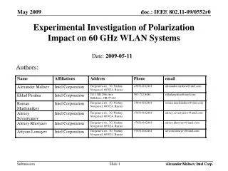
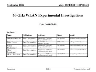
Inter Cluster Parameters of Living Room Channel Model for 60 GHz WLAN Systems Date:2009-11-16 Authors: Alexander Maltsev, Intel
Abstract • This contribution describes inter cluster parameters of the channel model for the home living room environment proposed to TGad. Alexander Maltsev, Intel
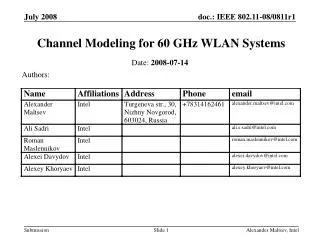
Introduction • The TGad draft EVM document [1] defines three channel modeling scenarios for TGad: small conference room, home living room, and cubicle environment. • The current version of the channel modeling document [2] proposes the general structure of the channel model and defines parameters for the conference room scenario. • This contribution presents inter cluster parameters for the channel model for 60 GHz WLAN systems in the home living room environment. Alexander Maltsev, Intel
Modeling Scenario for Home Living Room Environment • According to the EVM, in the home living room scenario, communication is done between a set top box (STB) transmitting uncompressed video and TV receiving uncompressed video. • The TV is placed in the middle of one of the walls at height of 1.5m. According to the EVM, the STB is at the same height above the floor as the TV. • Position of the STB can be different. The rectangular sector of possible user device positions in the horizontal plane was introduced (see Figure). • The average distance the STB and the TV was approximately 3-4 m as required in EVM. Alexander Maltsev, Intel
Parameters of Home Living Room Channel Model • Complete characterization of the channel model for the home living room scenario includes definition of: • Inter cluster time and angular parameters • Statistical models for the reflection coefficients of typical walls, ceiling, and floor surfaces (materials) of living rooms • Intra cluster time and angular parameters • Polarization impact model • This presentation provides a description of the inter cluster parameters of the home living room channel model. • The presented data is planned to be a basis for further development of the channel model. Alexander Maltsev, Intel
Experimental Results • A set of measurements was carried out in a big conference room with the dimensions approximately equal to the dimensions of the home living room in the EVM. Office furniture was removed from the room and armchairs and sofas were placed instead to model the living room environment. • The results of the measurements have demonstrated that communication may be established using LOS and first and second reflections from the room’s walls, ceiling, and floor (i.e. the same mechanisms as for the conference room scenario). • The angular positions of the clusters were in very good accordance with the positions of the signal propagated paths predicted using image based ray tracing. Alexander Maltsev, Intel
Full and Partial Blockage of Clusters • The experimental results revealed that not all the clusters are available for communication because some of the clusters blocked by humans or other obstacles or gone away from the room through the open door. As in the conference room scenario that effect was modeled by introducing the probability of cluster blockage. • A new effect was partial blocking (attenuation) of part of the clusters by penetration through armchairs and sofas (with and without people sitting on them). That effect is planned to be added to the channel model as a statistical attenuation model that would have a random magnitude and a random probability of occurrence. Alexander Maltsev, Intel
Inter Cluster Parameters • This presentation describes the inter cluster parameters for the home living room channel model that were obtained using the methodology of channel model development with the help of ray tracing proposed in [2]. • According to that methodology, to remove a limitation of small number of experimental measurements, ray tracing simulations are used to generate multiple realizations of the channel model clusters to facilitate development of statistical models for clusters parameters. • This contributions provides statistical models for inter cluster temporal and spatial (angular) parameters for the home living room channel model developed using the ray tracing methodology. • Definition of parameters for clusters blocking and attenuation, models for the reflection coefficients, polarization impact model, and intra cluster parameters is planned to be considered in other contributions. Alexander Maltsev, Intel
3D Model of Home Living Room Environment Used for Ray-tracing • A ray tracing model of the conference room with dimensions 7 x 7 x 3 m has been used to generate multiple realizations of 1st and 2nd order reflected clusters. Alexander Maltsev, Intel
Groups of Clusters • To allow more accurate channel modeling, all possible clusters are divided into several groups where clusters in the same group have similar properties. • There are 6 groups of clusters for the considered geometry of the home living room environment. The total number of clusters is equal to 19 (blocked and attenuated cluster are also counted) and the number of clusters in each group is constant for every channel realization and is given in table below. Alexander Maltsev, Intel
LOS Path • The LOS path is modeled as a single ray with the gain equal to: A0= λ/(4d) • where λis the wavelength and d is the distance between TX and RX. • The LOS component has zero TX and RX azimuth and elevation angles and also zero time of arrival (TOA). • The TX and RX elevation and azimuth angles, as well as arrival times of other clusters are defined relative to the LOS path. Alexander Maltsev, Intel
1st Order Reflections from Walls • There are three clusters corresponding to first order reflections from walls. There is one reflection per wall for all walls except for wall #3 where the TV is mounted. Reflection from wall #3 does not exist since the RX is placed near this wall. Alexander Maltsev, Intel
1st Order Reflections from Walls (Cont’d) • The model for generating the clusters corresponding to the first order wall reflections takes into account the following properties: • Elevation angle is equal to zero for all clusters at both TX and RX. • There are always two positive and one negative angles (or one positive and two negative angles) when considering TX azimuth angles of all three clusters. At the RX side there are also two positive and one negative (or one positive and two negative) azimuth angles. • Every cluster has either positive TX and negative RX azimuth angles, or, vise versa, negative TX and positive RX azimuth angles. • Considering a pair of clusters with positive TX and negative RX azimuth angles, a cluster with the larger absolute value of TX azimuth angle will have a smaller (than other cluster) absolute value of the RX azimuth angle. Correspondingly the cluster with smaller absolute TX azimuth angle will have a larger absolute RX azimuth angle. The same is true for the pair of clusters with negative TX and positive RX azimuth angles. Alexander Maltsev, Intel
1st Order Reflections from Walls (Cont’d) • The azimuth angles are generated simultaneously for pairs of clusters having the same signs of azimuth angles. After that one cluster corresponding to reflection from wall #3 (see slide 12) is excluded. The joint distribution for the pairs of azimuth angles on TX and RX sides is shown in the next slide. • The joint distribution is used to maintain necessary relationships between angular characteristics of different clusters. • It can be seen that there are no 1st order clusters which are closely spaced in the angular domain. Alexander Maltsev, Intel
Joint Distributions of Azimuth Angles with Same Sign for Two Clusters Corresponding to 1st Order Reflections TX side RX side Alexander Maltsev, Intel
Approximations for Azimuth Angles for 1st Order Wall Clusters • The following distribution (uniform in the given areas) has been used in the conference room channel model for the joint PDF approximation. TX side RX side Alexander Maltsev, Intel
1st Order Reflection from Ceiling and Floor • There are two clusters corresponding to 1st order reflections from ceiling and floor: • Azimuth angles are equal to zero for TX and RX • Elevation angles are equal to each other on TX and RX sides • Clusters reflected from ceiling and floor have equal absolute values of their elevation angles but opposite signs (the positive sign for the ceiling cluster and the negative sign for the floor cluster). Alexander Maltsev, Intel
2nd Order Reflections from Walls • There are total 5 clusters corresponding to the second order reflections from walls • These clusters have elevation angles equal to zero • The RX azimuth angles for these clusters are equal to either the TX azimuth angle or TX azimuth angle +/- 1800. Alexander Maltsev, Intel
Example of Five Clusters Corresponding to 2nd Reflections from Walls • For three clusters reflected from parallel walls, the azimuth angles at the TX and RX are equal to each other. • For two clusters reflected from perpendicular walls, TX and RX azimuth angles are shifted by +/- 1800. Alexander Maltsev, Intel
Empirical Distributions and Their Approximations of Azimuth Angles on TX Side for 2nd Order Clusters Reflected from Parallel Walls • The azimuth angles for clusters reflected from parallel walls are generated independently. Alexander Maltsev, Intel
Empirical Distributions and Their Approximations of Azimuth Angles on TX Side for 2nd Order Clusters Reflected from Perpendicular Walls • The azimuth angles for the clusters reflected from perpendicular walls (1-4, 4-1) and (1-2, 2-1) are generated independently. • But it is taken into account that the reflections from walls 4-1 and 2-1 cannot occur simultaneously. • Therefore, when this combination of the reflections occurs, the azimuth angles are discarded and the generation is repeated until the allowed combination of the reflections is obtained. Alexander Maltsev, Intel
2nd Order Reflections from Ceiling and Floor • There are two clusters corresponding to 2nd order reflections from ceiling and floor. • Azimuth angles for these clusters are equal to zero for TX and RX • Elevation angles for ceiling-floor and floor-ceiling reflection clusters have equal absolute values and opposite signs on TX and RX sides Alexander Maltsev, Intel
2nd Order Reflections from Walls and Ceiling or Walls and Floor • There are six clusters corresponding to the second order reflections from a wall and then the ceiling (floor) or the ceiling (floor) and then a wall. • The six reflections may be arranged into three sub-groups where each sub-group will include two clusters reflected from the wall and the ceiling for one cluster and the floor for another. (The above properties follows from a symmetry of the STB and TV positions relatively to the floor and ceiling.) Hence, only once cluster for each pair may be generated and the other cluster will have the same parameters except for the elevation angle that will have different sign. • The azimuth angles of the clusters are equal to the azimuth angles of the corresponding first order reflected clusters from walls. Alexander Maltsev, Intel
2nd Order Reflections from Walls and Ceiling or Walls and Floor (Cont’d) • The table presents possible types of the reflections in the considered home living room environment and their probabilities. Note that reflections from the wall with the TV (wall #3) are not considered because the RX is placed near to this wall and the reflections are not possible. Alexander Maltsev, Intel
Elevation Angles Distributions for 2nd Order Reflections from Walls and Ceiling or Walls and Floor • Due to symmetry the distributions of the elevation angle for ceiling (floor) – wall #2 and ceiling (floor) – wall #4 clusters are the same. Also this is true for clusters wall #2 – ceiling (floor) and wall #4 – ceiling (floor). • Only 3 distributions for elevation angle should be derived to describe all elevation angles dependences. Alexander Maltsev, Intel
Cluster Time of Arrival (TOA) for 1st Order Reflections • TOA is calculated relative to the LOS • Measured (using ray tracing) distributions are shown as solid lines • Approximations are shown as dashed lines • TOAs for all clusters within different 1st order cluster groups are generated independently Alexander Maltsev, Intel
Cluster Time of Arrival (TOA) for 2nd Order Reflections • TOA is calculated relative to the LOS • Ray tracing simulations are solid curves; approximations are dashed lines • TOAs for all clusters within different 2st order cluster groups are generated independently (but TOAs are equal for the clusters inside one pair of the reflections from walls and ceiling or walls and floor Alexander Maltsev, Intel
Conclusion • This presentation proposed inter cluster parameters for the home living room scenario of the TGad channel model. • An update of the channel model document [2] will be provided with the description of the developed inter cluster parameters, including equations for the approximations. • To complete the home living room channel model development, the following parameters have to be identified: • Parameters of clusters blockage and attenuation (by furniture items) • Statistical models for the reflection coefficients of typical walls, ceiling, and floor surfaces (materials) of living rooms • Intra cluster time and angular parameters • Polarization impact model • Collaboration with other companies and institutes interested in contribution to the TGad channel modeling work is required to complete the home living room as well as cubicle environment channel models Alexander Maltsev, Intel
References • IEEE doc. 802.11-09/0096r8. TGad evaluation methodology, E. Perahia, July , 2009. • IEEE doc. 802.11-09/0334r3. Channel models for 60 GHz WLAN systems, A. Maltsev et al, July, 2009. Alexander Maltsev, Intel