Understanding Internet Basics and Infrastructure
Explore the fundamentals of the Internet, network protocols, and performance metrics. Learn about network edge, core structure, security layers, and service models. Discover the history and evolution of the Internet as a network of networks. Dive into topics such as access networks, protocol layers, and communication infrastructure enabling various applications. Understand different access technologies like DSL, cable modems, and wireless networks.

Understanding Internet Basics and Infrastructure
E N D
Presentation Transcript
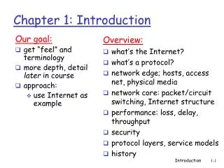
Our goal: get “feel” and terminology more depth, detail later in course approach: use Internet as example Overview: what’s the Internet? what’s a protocol? network edge; hosts, access net, physical media network core: packet/circuit switching, Internet structure performance: loss, delay, throughput security protocol layers, service models history Chapter 1: Introduction Introduction
millions of connected computing devices: hosts = end systems running network apps PC Mobile network server Global ISP wireless laptop cellular handheld Home network Regional ISP access points wired links Institutional network router What’s the Internet: “nuts and bolts” view • communication links • fiber, copper, radio, satellite • transmission rate = bandwidth • routers: forward packets (chunks of data) Introduction
protocolscontrol sending, receiving of msgs e.g., TCP, IP, HTTP, Skype, Ethernet Internet: “network of networks” loosely hierarchical public Internet versus private intranet Internet standards RFC: Request for comments IETF: Internet Engineering Task Force Mobile network Global ISP Home network Regional ISP Institutional network What’s the Internet: “nuts and bolts” view Introduction
communication infrastructure enables distributed applications: Web, VoIP, email, games, e-commerce, file sharing communication services provided to apps: reliable data delivery from source to destination “best effort” (unreliable) data delivery What’s the Internet: a service view Introduction
end systems (hosts): run application programs e.g. Web, email at “edge of network” peer-peer client/server The network edge: • client/server model • client host requests, receives service from always-on server • e.g. Web browser/server; email client/server • peer-peer model: • minimal (or no) use of dedicated servers • e.g. Skype, BitTorrent Introduction
Q: How to connect end systems to edge router? residential access nets institutional access networks (school, company) mobile access networks Keep in mind: bandwidth (bits per second) of access network? shared or dedicated? Access networks and physical media Introduction
Dial-up Modem central office telephone network Internet homedial-up modem ISPmodem (e.g., AOL) home PC • Uses existing telephony infrastructure • Home is connected to central office • up to 56Kbps direct access to router (often less) • Can’t surf and phone at same time: not “always on”
telephone network Digital Subscriber Line (DSL) Existing phone line:0-4KHz phone; 4-50KHz upstream data; 50KHz-1MHz downstream data Internet home phone DSLAM splitter DSL modem central office home PC • Also uses existing telephone infrastruture • up to 1 Mbps upstream (today typically < 256 kbps) • up to 8 Mbps downstream (today typically < 1 Mbps) • dedicated physical line to telephone central office
Does not use telephone infrastructure Instead uses cable TV infrastructure HFC: hybrid fiber coax asymmetric: up to 30Mbps downstream, 2 Mbps upstream network of cable and fiber attaches homes to ISP router homes share access to router unlike DSL, which has dedicated access Residential access: cable modems Introduction
Cable Network Architecture: Overview cable headend home cable distribution network (simplified) Introduction
ONT ONT ONT Fiber to the Home opticalfibers Internet • Optical links from central office to the home • Two competing optical technologies: • Passive Optical network (PON) • Active Optical Network (PAN) • Much higher Internet rates; fiber also carries television and phone services opticalfiber OLT optical splitter central office
Ethernet Internet access • Typically used in companies, universities, etc • 10 Mbs, 100Mbps, 1Gbps, 10Gbps Ethernet • Today, end systems typically connect into Ethernet switch 100 Mbps Institutional router To Institution’sISP Ethernet switch 100 Mbps 1 Gbps 100 Mbps server
shared wireless access network connects end system to router via base station aka “access point” wireless LANs: 802.11b/g (WiFi): 11 or 54 Mbps wider-area wireless access provided by telco operator ~1Mbps over cellular system (EVDO, HSDPA) next up (?): WiMAX (10’s Mbps) over wide area Wireless access networks router base station mobile hosts Introduction
Typical home network components: DSL or cable modem router/firewall/NAT Ethernet wireless access point Home networks wireless laptops to/from cable headend cable modem router/ firewall wireless access point Ethernet Introduction
Bit: propagates betweentransmitter/rcvr pairs physical link: what lies between transmitter & receiver guided media: signals propagate in solid media: copper, fiber, coax unguided media: signals propagate freely, e.g., radio Twisted Pair (TP) two insulated copper wires Category 3: traditional phone wires, 10 Mbps Ethernet Category 5: 100Mbps Ethernet Physical Media Introduction
Coaxial cable: two concentric copper conductors bidirectional baseband: single channel on cable legacy Ethernet broadband: multiple channels on cable HFC Physical Media: coax, fiber Fiber optic cable: • glass fiber carrying light pulses, each pulse a bit • high-speed operation: • high-speed point-to-point transmission (e.g., 10’s-100’s Gps) • low error rate: repeaters spaced far apart ; immune to electromagnetic noise Introduction
signal carried in electromagnetic spectrum no physical “wire” bidirectional propagation environment effects: reflection obstruction by objects interference Physical media: radio Radio link types: • terrestrial microwave • e.g. up to 45 Mbps channels • LAN (e.g., Wifi) • 11Mbps, 54 Mbps • wide-area (e.g., cellular) • 3G cellular: ~ 1 Mbps • satellite • Kbps to 45Mbps channel (or multiple smaller channels) • 270 msec end-end delay • geosynchronous versus low altitude Introduction
mesh of interconnected routers the fundamental question: how is data transferred through net? circuit switching: dedicated circuit per call: telephone net packet-switching: data sent thru net in discrete “chunks” The Network Core Introduction
End-end resources reserved for “call” link bandwidth, switch capacity dedicated resources: no sharing circuit-like (guaranteed) performance call setup required Network Core: Circuit Switching Introduction
network resources (e.g., bandwidth) divided into “pieces” pieces allocated to calls resource piece idle if not used by owning call (no sharing) Network Core: Circuit Switching • dividing link bandwidth into “pieces” • frequency division • time division Introduction
Example: 4 users FDM frequency time TDM frequency time Circuit Switching: FDM and TDM Introduction
each end-end data stream divided into packets user A, B packets share network resources each packet uses full link bandwidth resources used as needed Bandwidth division into “pieces” Dedicated allocation Resource reservation Network Core: Packet Switching resource contention: • aggregate resource demand can exceed amount available • congestion: packets queue, wait for link use • store and forward: packets move one hop at a time • Node receives complete packet before forwarding Introduction
1 Mb/s link each user: 100 kb/s when “active” active 10% of time circuit-switching: 10 users packet switching: with 35 users, probability > 10 active at same time is less than .0004 Packet switching allows more users to use network! Packet switching versus circuit switching N users 1 Mbps link Q: how did we get value 0.0004? Introduction
great for bursty data resource sharing simpler, no call setup excessive congestion: packet delay and loss protocols needed for reliable data transfer, congestion control Q: How to provide circuit-like behavior? bandwidth guarantees needed for audio/video apps still an unsolved problem (chapter 7) Is packet switching a “slam dunk winner?” Packet switching versus circuit switching Q: human analogies of reserved resources (circuit switching) versus on-demand allocation (packet-switching)? Introduction
roughly hierarchical at center: “tier-1” ISPs (e.g., Verizon, Sprint, AT&T, Cable and Wireless), national/international coverage treat each other as equals Tier-1 providers interconnect (peer) privately Internet structure: network of networks Tier 1 ISP Tier 1 ISP Tier 1 ISP Introduction
POP: point-of-presence to/from backbone peering … …. … … … to/from customers Tier-1 ISP: e.g., Sprint Introduction
“Tier-2” ISPs: smaller (often regional) ISPs Connect to one or more tier-1 ISPs, possibly other tier-2 ISPs Tier-2 ISPs also peer privately with each other. • Tier-2 ISP pays tier-1 ISP for connectivity to rest of Internet • tier-2 ISP is customer of tier-1 provider Tier-2 ISP Tier-2 ISP Tier-2 ISP Tier-2 ISP Tier-2 ISP Internet structure: network of networks Tier 1 ISP Tier 1 ISP Tier 1 ISP Introduction
“Tier-3” ISPs and local ISPs last hop (“access”) network (closest to end systems) Tier 3 ISP local ISP local ISP local ISP local ISP local ISP local ISP local ISP local ISP Local and tier- 3 ISPs are customers of higher tier ISPs connecting them to rest of Internet Tier-2 ISP Tier-2 ISP Tier-2 ISP Tier-2 ISP Tier-2 ISP Internet structure: network of networks Tier 1 ISP Tier 1 ISP Tier 1 ISP Introduction
a packet passes through many networks! Tier 3 ISP local ISP local ISP local ISP local ISP local ISP local ISP local ISP local ISP Tier-2 ISP Tier-2 ISP Tier-2 ISP Tier-2 ISP Tier-2 ISP Internet structure: network of networks Tier 1 ISP Tier 1 ISP Tier 1 ISP Introduction
packets queue in router buffers packet arrival rate to link exceeds output link capacity packets queue, wait for turn packet being transmitted (delay) packets queueing (delay) free (available) buffers: arriving packets dropped (loss) if no free buffers How do loss and delay occur? A B Introduction
1. nodal processing: check bit errors determine output link transmission A propagation B nodal processing queueing Four sources of packet delay • 2. queueing • time waiting at output link for transmission • depends on congestion level of router Introduction
3. Transmission delay: R=link bandwidth (bps) L=packet length (bits) time to send bits into link = L/R 4. Propagation delay: d = length of physical link s = propagation speed in medium (~2x10⁸ m/sec) propagation delay = d/s transmission A propagation B nodal processing queueing Delay in packet-switched networks Note: s and R are very different quantities! Introduction
Nodal delay • dproc = processing delay • typically a few microsecs or less • dqueue = queuing delay • depends on congestion • dtrans = transmission delay • = L/R, significant for low-speed links • dprop = propagation delay • a few microsecs to hundreds of msecs Introduction
“Real” Internet delays and routes • What do “real” Internet delay & loss look like? • Traceroute program: provides delay measurement from source to router along end-end Internet path towards destination. For all i: • sends three packets that will reach router i on path towards destination • router i will return packets to sender • sender times interval between transmission and reply. 3 probes 3 probes 3 probes Introduction
“Real” Internet delays and routes traceroute: gaia.cs.umass.edu to www.eurecom.fr Three delay measurements from gaia.cs.umass.edu to cs-gw.cs.umass.edu 1 cs-gw (128.119.240.254) 1 ms 1 ms 2 ms 2 border1-rt-fa5-1-0.gw.umass.edu (128.119.3.145) 1 ms 1 ms 2 ms 3 cht-vbns.gw.umass.edu (128.119.3.130) 6 ms 5 ms 5 ms 4 jn1-at1-0-0-19.wor.vbns.net (204.147.132.129) 16 ms 11 ms 13 ms 5 jn1-so7-0-0-0.wae.vbns.net (204.147.136.136) 21 ms 18 ms 18 ms 6 abilene-vbns.abilene.ucaid.edu (198.32.11.9) 22 ms 18 ms 22 ms 7 nycm-wash.abilene.ucaid.edu (198.32.8.46) 22 ms 22 ms 22 ms 8 62.40.103.253 (62.40.103.253) 104 ms 109 ms 106 ms 9 de2-1.de1.de.geant.net (62.40.96.129) 109 ms 102 ms 104 ms 10 de.fr1.fr.geant.net (62.40.96.50) 113 ms 121 ms 114 ms 11 renater-gw.fr1.fr.geant.net (62.40.103.54) 112 ms 114 ms 112 ms 12 nio-n2.cssi.renater.fr (193.51.206.13) 111 ms 114 ms 116 ms 13 nice.cssi.renater.fr (195.220.98.102) 123 ms 125 ms 124 ms 14 r3t2-nice.cssi.renater.fr (195.220.98.110) 126 ms 126 ms 124 ms 15 eurecom-valbonne.r3t2.ft.net (193.48.50.54) 135 ms 128 ms 133 ms 16 194.214.211.25 (194.214.211.25) 126 ms 128 ms 126 ms 17 * * * 18 * * * 19 fantasia.eurecom.fr (193.55.113.142) 132 ms 128 ms 136ms trans-oceanic link * means no response (probe lost, router not replying) Introduction
Packet loss • queue (aka buffer) preceding link in buffer has finite capacity • packet arriving to full queue dropped (aka lost) • lost packet may be retransmitted by previous node, by source end system, or not at all buffer (waiting area) packet being transmitted A B packet arriving to full bufferis lost Introduction
pipe that can carry fluid at rate Rsbits/sec) pipe that can carry fluid at rate Rcbits/sec) Throughput • throughput: rate (bits/time unit) at which bits transferred between sender/receiver • instantaneous: rate at given point in time • average: rate over longer period of time link capacity Rcbits/sec link capacity Rsbits/sec server, with file of F bits to send to client server sends bits (fluid) into pipe Introduction
Rs > RcWhat is average end-end throughput? Rsbits/sec Rcbits/sec Rcbits/sec bottleneck link link on end-end path that constrains end-end throughput Throughput (more) • Rs < RcWhat is average end-end throughput? Rsbits/sec Introduction
Throughput: Internet scenario • per-connection end-end throughput: min(Rc,Rs,R/10) • in practice: Rc or Rs is often bottleneck Rs Rs Rs R Rc Rc Rc 10 connections (fairly) share backbone bottleneck link Rbits/sec Introduction
Networks are complex! many “pieces”: hosts routers links of various media applications protocols hardware, software Question: Is there any hope of organizing structure of network? Or at least our discussion of networks? Protocol “Layers” Introduction
Why layering? Dealing with complex systems: • explicit structure allows identification, relationship of complex system’s pieces • layered reference model for discussion • modularization eases maintenance, updating of system • change of implementation of layer’s service transparent to rest of system • e.g., change in gate procedure doesn’t affect rest of system • layering considered harmful? Introduction
application: supporting network applications FTP, SMTP, HTTP transport: process-process data transfer TCP, UDP network: routing of datagrams from source to destination IP, routing protocols link: data transfer between neighboring network elements PPP, Ethernet physical: bits “on the wire” application transport network link physical Internet protocol stack Introduction
network link physical link physical M M M Ht M Hn Hn Hn Hn Ht Ht Ht Ht M M M M Ht Ht Hn Hl Hl Hl Hn Hn Hn Ht Ht Ht M M M source Encapsulation message application transport network link physical segment datagram frame switch destination application transport network link physical router Introduction
Introduction: Summary Covered a “ton” of material! Internet overview what’s a protocol? network edge, core, access network packet-switching versus circuit-switching Internet structure performance: loss, delay, throughput layering, service models security history You now have: context, overview, “feel” of networking more depth, detail to follow! Introduction 1-44