Design of a Variable Pressure Gradient Wind Tunnel
20 likes | 346 Vues
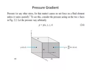
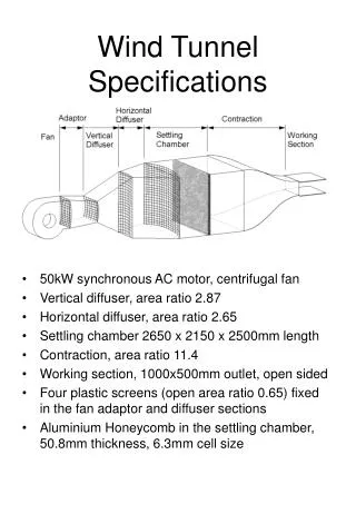
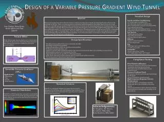
- DRAG Engineering-. Detailed Design Nozzle and Flow Conditioning ¼” honeycomb to straighten flow Two fine mesh screens to condition flow Flow cutoff system to prevent cavity flow within flow conditioning section Fifth order polynomial inlet geometry

Design of a Variable Pressure Gradient Wind Tunnel
E N D
Presentation Transcript
-DRAG Engineering- • Detailed Design • Nozzle and Flow Conditioning • ¼” honeycomb to straighten flow • Two fine mesh screens to condition flow • Flow cutoff system to prevent cavity flow within flow conditioning section • Fifth order polynomial inlet geometry • Adjustable ceiling to match test section ceiling • Test Section • Flexible geometry ceiling • Polycarbonate windows • Fourteen Pressure taps in floor • Diffuser • Square to round transition • Conical sheet metal • Fan • EBM Papst 230V, 60Hz Tubeaxial Fan • 0.4 inH20 at 320cfm • Controller • GS1 AC micro drive, 0.25 hp • 120V single-phase input, 230V output Abstract Many recent studies have shown that the manner in which a boundary layer initially develops significantly influences the remainder of the flow. There are many situations in which the initial development of boundary layers occurs on a rough surface in a favorable pressure gradient (FPG) environment. For instance, the initial development of a boundary layer over a submarine hull occurs under these circumstances. Despite their frequent occurrence, FPG rough boundary layers have not yet been sufficiently studied. It is for this reason that the University of Wyoming Aeronautical Laboratories (UWAL) is interested in studying these types of boundary layers. However, UWAL does not currently possess a wind tunnel capable of accurately and consistently producing favorable pressure gradients. It is for this reason that it is necessary to design and build a new tunnel to meet the testing needs of the laboratory. Design of a Variable Pressure Gradient Wind Tunnel • Venturi Effect • Fluid velocity must increase at point 2 to conserve mass • As fluid velocity increases, the static pressure decreases • Decreasing static pressure is defined as a favorable pressure gradient • Design Specifications • Variable pressure gradient from zero to extremely favorable • Smoothly varying pressure gradient • Adjustable geometry to allow for variable pressure gradient • Turbulence intensity less than 0.2% • Uniform core flow with a maximum velocity of 60 meters/second and less than 0.5% variability in mean velocity • Wall boundary layers do not contaminate core flow • High quality optical access possible for LDA measurements • Walls can be removed in under 5 minutes each, for quick access to the test section • Floor instrumented with pressure taps every 2 cm Sean Dunlop, Bryon Riotto, Shawn Allred, and Chad Gagnon • Compliance Testing • Wind Tunnel Calibration • Determine velocity as a function of fan frequency • Determine maximum tunnel velocity • Pitot static tube and differential pressure transducer used • Pressure Gradient Check • Determine if the test section design meets design specifications • 16 port PSI pressure transducer used • High Frequency Response Velocity Measurement • Ensure less than 0.2% turbulence intensity • Ensure less than 0.5% variability in the mean velocity • Hotwire Anemometry used to determine the free stream turbulence intensity and variability in the mean velocity • Favorable Pressure Gradients • (FPG) • Applications • Submarines • Ships • Aircraft • Wind Turbines Numerical Solutions Eddy BL is a numerical simulation program that was used to determine the wall shear stress and boundary layer thickness. These values were then used to determine the required pressure gradient and test section geometry. Numerical Simulations FLUENT is a CFD Program that was used to reveal details of the flow as well as to check the tunnel geometry for any issues. Velocity vectors can be seen below for a moderate pressure gradient. Solutions for Aerodynamic Testing Acknowledgements: Dr. Naughton, Mr. Morton, Dr. Erikson, Mike Allen, Korey Kreitman, Mike Schilt