
SlideServe
Menu
Préférences
© SlideServe · v2026

Wind Tunnel Specifications

lefty avatar
9 diapositives · 811 Views · Aug 08, 2014

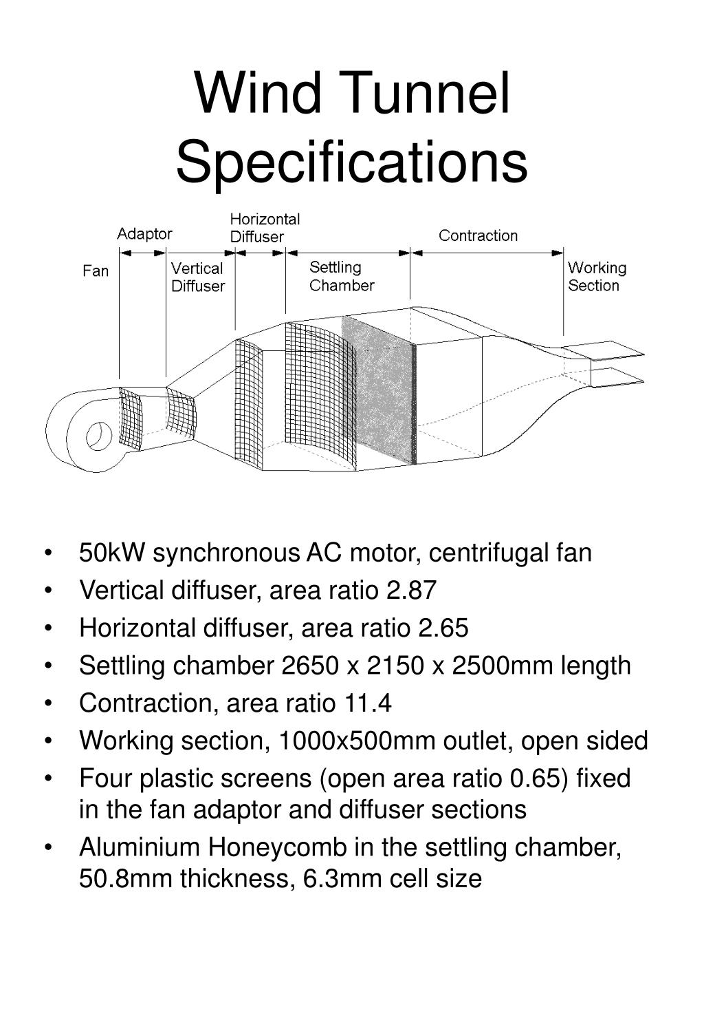
Wind Tunnel Specifications. 50kW synchronous AC motor, centrifugal fan Vertical diffuser, area ratio 2.87 Horizontal diffuser, area ratio 2.65 Settling chamber 2650 x 2150 x 2500mm length Contraction, area ratio 11.4 Working section, 1000x500mm outlet, open sided
Wind Tunnel Specifications - slide 1
01 / 9Wind Tunnel Specifications
1 / 17

Télécharger la présentation

Wind Tunnel Specifications
Une image / un lien ci-dessous est fourni (tel quel) pour télécharger la présentation

Politique de téléchargement : le contenu du site vous est fourni TEL QUEL pour votre information et votre usage personnel ; il ne peut être vendu, concédé sous licence ni partagé sur d’autres sites sans l’accord de son auteur.Le contenu vous est fourni TEL QUEL, pour votre information et votre usage personnel uniquement. Téléchargez la présentation en cliquant sur ce lien. Lors du téléchargement, si vous ne parvenez pas à télécharger une présentation, l’éditeur a peut-être supprimé le fichier de son serveur.Pendant le téléchargement, si vous ne parvenez pas à obtenir une présentation, le fichier a peut-être été supprimé par l’éditeur.

F I N

Plus de contenu associé

Transcription de la présentation
  1. Wind Tunnel Specifications • 50kW synchronous AC motor, centrifugal fan • Vertical diffuser, area ratio 2.87 • Horizontal diffuser, area ratio 2.65 • Settling chamber 2650 x 2150 x 2500mm length • Contraction, area ratio 11.4 • Working section, 1000x500mm outlet, open sided • Four plastic screens (open area ratio 0.65) fixed in the fan adaptor and diffuser sections • Aluminium Honeycomb in the settling chamber, 50.8mm thickness, 6.3mm cell size

  2. Flow Uniformity • Flow velocity contours at tunnel outlet without working section 5 m/s 10 m/s 15 m/s

  3. Flow Uniformity • Flow velocity is within 1% of mean velocity across the 1m x 0.5m working section outlet Velocity contours in working section 5 m/s 10 m/s

  4. A B 200mm Horizontal Wind Gradient • Mean pressures A & B measured simultaneously with two pitot-static tubes spanning 200mm at the anemometer cup location. Procedure repeated with p-s tubes reversed. • Linear regression shows 0.3% difference in pressure

  5. Turbulence Measurements single normal hotwire Pitot-static tube (design similar to AMCA type) anemometer & filter (5kHz) Pressure Transducer Ashcroft XLdp Analog-Digital Converter NI PCI-6013 (16 bit) PC

  6. Turbulence Intensity Turbulence Intensity

  7. Wind Tunnel Turbulence Spectra

  8. p-s probe location Cup Anemometer Calibration Setup

  9. Calibration Procedure Pitot-static tube (design similar to AMCA type) • Risoe P2546A cup anemometer calibrated using the Measnet procedure • No blockage included for Newcastle result Pressure Transducer Ashcroft XLdp HP Frequency Counter Analog-Digital Converter NI PCI-6013 (16 bit) PC