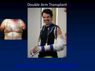
Enhancements in Double Arm Juggling System: Control and Camera Development Progress
240 likes | 353 Vues
This presentation outlines the progress made by the ECSE-4962 team on the Double Arm Juggling System project. The bulk of the design and build are complete, transitioning into testing and tuning phases. Key topics include advancements in physical design, control systems, camera development, and challenges faced, such as net design and material modifications. The team has utilized advanced modeling techniques and control methods to optimize system performance. Preliminary results are promising, indicating effective trajectory predictions and control systems integration.

Enhancements in Double Arm Juggling System: Control and Camera Development Progress
E N D
Presentation Transcript
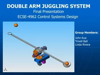
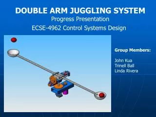
DOUBLE ARM JUGGLING SYSTEM Progress Presentation ECSE-4962 Control Systems Design Group Members: John Kua Trinell Ball Linda Rivera
Introduction • Where are we? • Bulk of Design and Build Complete • Testing and Tuning Phase • Preliminary Results • Physical Design • Model Development • Control Systems Development • Camera Development
Physical Design • Additions: • Camera Mounting • Overall System Mounting • Other physical modifications • Shaft Mounting • Cable extensions • Challenges: • Net Design • Material • Building • Possible solutions: • Foil wrapping current nets • Replacing nets • h Camera Mounting Shaft Mounting System Mounting
Model Development • Lagrange-Euler Model • Single Joint
DAC to Current Model • Digital to Analog Conversion • Tested voltage over a range • Fit curve to data – found slope, offset • Voltage to Current Conversion • Adjusted gain to approximately 0.1A/V • Tested current over a range • Applied load to system for accurate measurement
Friction Identification • Identify Viscous and Coulomb Friction • Apply constant torque and measure steady state velocity • Automate with LabVIEW • Process data with MATLAB
Other Parameters • Inertia/Mass • Calculated with SolidWorks • Shaft Spring Constant • Possible cause of oscillations • Experimentally measured • Found to be very stiff - k=4600N/m
Model Linearization • Discard Coulomb Friction • State Space Equations • Transfer Function
Model Verification • Compare Friction ID results to simulated “Friction ID” • Compare simulated controlled output to implemented output • Potentially apply “chirp” ID methods
Velocity Estimation • Finite difference method – 10ms • Minimum velocity of 0.1534 rad/sec • Maximum motor speed of 21 rad/sec • Designed peak velocity of 15 rad/sec • Overflow problem • Seeing large velocity pulse in data • Limited position to +/- 180 degrees • Corrected velocity when over limits (153 rad/sec)
Trajectory Calculation • Drag force on the ball • Trajectory deviates from standard projectile motion equation • Differential Equation • Iterative vs. Simulink ODE Solver
Control Systems Development • Two methods for designing controllers used • MATLAB rltool (Pole Placement method) • 1. Obtain transfer function • 2. Import transfer function to rltool • 3. Convert continuous model to discrete model (sampling time 10ms) • 4. Define design constraints, such as rise time and settling time • 5. Place gain constant at the crossings of design constraints • 6. Export controller to simulink model of system • 7. Run simulation to test • PID block MATLAB (simulink) • Kp = Proportional • Ki = Integral • Kd = Derivative
Pole Placement Methods Tilt-System Root Locus Design Criteria • Closed Loop poles Stable • Locate system poles at the • intersection of ωn and ς ωn = 62.8 rad/s ς = .7
Kp = 800 Ki = 20 Kd = 40 Non-Linear System Step Response To different controllers rltool controller PID controller Overshoot: 28.7% Overshoot: 0%
Camera Development • Vision Module Familiarization: • Use of NI Vision Assistant • Acquire Preliminary data • Carry out a number of tests • Image ProcessingExamples: • Projectile motion launch
Upward vertical launch Processing Challenges: • Blurred images of the ball • Colored backgrounds similar to ball’s color Image 9/30 Image 12/30
Ball blur 1. 2. 3.
Background similar to ball color • Possible solutions: • Blur Take average of circles • Background Create uniform dark background
Data Verification: • Verify if height prediction data is valid • Run new experiment • Compare results • If results from script seem reasonable • Use Overhead camera only • If results form script are unreliable • Add Additional camera on the side • Next Steps: • Running Trajectory Prediction • Integration of Vision Development with Control System • Continue to validate data
Summary of Progress • Schedule • On track, only a few items outstanding • Costs • 10% overbudget, 20% under estimates • Did not purchase motor, built support structures • Plan of Action • No deviations • New Difficulties