DOUBLE ARM JUGGLING SYSTEM Final Presentation ECSE-4962 Control Systems Design
360 likes | 544 Vues
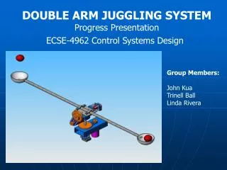
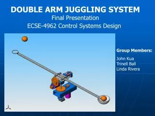
DOUBLE ARM JUGGLING SYSTEM Final Presentation ECSE-4962 Control Systems Design. Group Members: John Kua Trinell Ball Linda Rivera. Presentation Outline. Introduction Objectives System Specifications Plan of Action System Integration Physical Design Modeling Control System

DOUBLE ARM JUGGLING SYSTEM Final Presentation ECSE-4962 Control Systems Design
E N D
Presentation Transcript
DOUBLE ARM JUGGLING SYSTEM Final Presentation ECSE-4962 Control Systems Design Group Members: John Kua Trinell Ball Linda Rivera
Presentation Outline • Introduction • Objectives • System Specifications • Plan of Action • System Integration • Physical Design • Modeling • Control System • Camera Development • Results • Future Improvements
Introduction • Goal: To design and develop a juggling system mechanism • Pivoted double-ended arm • Able to handle two or more ping pong balls
Introduction • Motivation • Previous Project CSD Team 7 of 2004 • Single arm • Open loop • Research Project by Dr. D. E. Koditschek – University of Michigan • Tossed pucks vertically with single padded arm • Uses camera for feedback
Objectives • Develop mechanism to simultaneously juggle two or more balls • Execute toss and catch operations quickly • Provide feedback on arm’s state • Provide feedback on balls’ state • Predict trajectory of the ball • Design control system • Learn from toss/catch errors • Compensate for disturbances in flight path of the balls
Specifications • Flight Profile: x: 0.75m, t: 1s • Pan: Range of Motion – ±10° Max Accel: 34.9 rad/s2 Overshoot: <5% (pos) Settling Time: <0.1 sec Steady State Error: ±1° (±6.5mm) • Tilt: Range of Motion – ±30° Max Accel: 201.79 rad/s2 Launch (Max) Velocity: 5.4 m/s Overshoot: <5% (pos), <1% (vel) Settling Time: <0.1 sec Steady State Error: ±1° (±6.5mm) Can track 2Hz sinusoidal input
Parameter Analysis Develop Camera Subsystem Model Development Build System Model Verification X-Y Tracking Pan/Tilt Control Systems Design Z Tracking Vision Feedback Controller Design Trajectory Prediction Open Loop 1-D Testing Closed Loop 2-D Testing Open Loop 2-D Testing Open Loop Two Ball Juggle Closed Loop Two Ball Juggle Plan of Action
System Integration Vision Processing Laptop Parallel Port NI cRIO Controller
Code Structure (Vision) Video Stream In Frame Grab Image Processing Data Processing Pan Correction Calculation Tilt Correction Calculation
Code Structure (cRIO) FPGA Host EncoderInput User Interface Velocity Estimation Controller Parallel PortInput
Physical Design - Additions Camera Mounting Overall System Mounting
Other Physical Modifications Shaft Mounting Cable Extension Parallel Port
Fabric Foil Cones Challenges - Net Design Process
Final Net Design Tossing Catching
Modeling & Simulation • System: • Treat as Decoupled Links • Parameters: Motor Torque, Gear Ratios, Inertial Loads, Shaft Oscillations • Nonlinearities: Friction, Backlash, Noise • Linearize Model for Control Design • Trajectory: Projectile Motion, Drag
Model Development • Lagrange-Euler Model • Single Joint
Friction Identification • Identify Viscous and Coulomb Friction • Apply constant torque and measure steady state velocity • Automate with LabVIEW • Process data with MATLAB
Other Parameters • Inertia/Mass • Calculated with SolidWorks • Shaft Spring Constant • Possible cause of oscillations • Experimentally measured • Found to be very stiff - k=4600N/m
Trajectory Calculation • Drag force on the ball • Trajectory deviates from standard projectile motion equation • Differential Equation • Simulink ODE Solver
Control System • Tilt and Pan Axis: PID controller θt Controller Tilt Plant Tilt θt Shaft Dynamics θp Controller Pan Plant Pan θp Vision p,t Ball Dynamics
Control Systems Development • Two methods for designing controllers used • MATLAB rltool (Pole Placement method) • 1. Obtain transfer function (System Parameters) • 2. Define design constraints, such as rise time and settling time • 3. Run simulation to test • PID block MATLAB (simulink) • Kp = Proportional • Ki = Integral • Kd = Derivative
Non-Linear Simulation Step Response rltool controller PID controller Overshoot: 28.7% Overshoot: 0%
Camera Development • Image Processing • Data Verification • Trajectory Prediction • Pan • Tilt
Image Processing Script Original Image Threshold Circle Detection • Challenges Overcome • Blur Change shutter speed 1/100 sec • Extra circles Set black background
Data Verification • Rolling down the ramp experiment
Trajectory Prediction • Pan • Linear Curve Fit
Trajectory Prediction • Tilt • X Data Averaging Radius > 7 pixels Y x
Parallel Port • Standard networking VIs slow • FPGA can read digital inputs quickly • Write to Parallel Port to communicate with NI 9401 Digital I/O • Lines • Packet Start (1) • Data Ready (1) • Data (4)
Parallel Port Protocol • Toggle Packet Start • Write Data Type (Pan, Tilt) to Bus • Toggle Data Ready • Write Data to Bus Packet Start Data Ready Data Type Data Type Data Type Data
Results • Catching Accuracy • 30 tosses: catches made 83.3% • Can not catch overshoot, or undershoot beyond constraints • Tossing Accuracy • While setting ball on tossing ring, too much force can not be exerted otherwise launch initial conditions change • Belts are too tight Non-linear friction • Loosening belts can lead to slipping (trade off)
Controller Response - Pan • Overshoot0% (5%) • Settling Time 0.07s (0.1s) • Steady State Error 0.29° (±1°) • Rise Time0.1s
Controller Response - Tilt • Overshoot16% (5%) • Settling Time 0.3s (0.1s) • Steady State Error 0.34° (±1°) • Rise Time0.08s
Video • Play Video Here
Future Improvements • Implement Trajectory Generation • Better Controller (LQR) • Improve Height Estimation • Add second camera • Increase camera resolution (processing power) • Better way to transfer torque from motor to pan tilt joints other than existing belts • Juggling • System response not fast enough • Nets need dual-use optimization