Download
1 / 41
420 likes | 672 Vues
MAV Control System - P09122 - Final Design Review. Erik Bellandi – Project Manager Ben Wager – Lead Engineer Garrett Argenna – Mechanical Engineering Michael Pepen – Electrical Engineering Tahar Allag – Electrical Engineering Ramon Campusano – Computer Engineering

E N D
MAV Control System - P09122- Final Design Review Erik Bellandi – Project Manager Ben Wager – Lead Engineer Garrett Argenna – Mechanical Engineering Michael Pepen – Electrical Engineering Tahar Allag – Electrical Engineering Ramon Campusano – Computer Engineering Stephen Nichols – Computer Engineering
Contents • Objectives & Deliverables • Detailed Design • Logic Controller • Sensors • Control System • Test Stand • Power, Weight and Cost • Design Specifications • Plan for MSD II
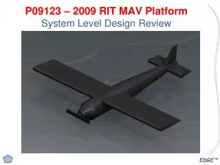
Project Objectives & Deliverables Product Description / Project Overview To design and build a flight control system for the Micro Aerial Vehicle, that will most quickly lead to a fully autonomous system. Key Business Goals / Project Deliverables Primary Goals: Make the MAV as autonomous as possible. Achieve desired flight qualities. Stabilize if unstable or increase damping Adaptable Fully Tested and Integrate with Platform Secondary Business Goal: Able to compete in the 2010 EMAV Competition.
Logic Controller Design • FPGA with microcontroller core • Open-source Plasma CPU core • License issues with prior Altera Nios Core • Dual core: • Control system core • Sensor communication core • UART communication (GPS sensor ) • SPI communication (IMU and SD card) • SD communication • Load programs from SD • Record sensor data • PWM communication (Pilot Input and Servo Output)
Logic Controller Prototype and Testing • Open Source Plasma CPU core • Instantiated core on FPGA • Tested UART communication between PC and Plasma core • SD communication • Initialized SD card into SPI mode • Read MBR and FAT16 • Implemented file read capability • PWM • Implemented and tested PWM feed-through
Sensor Design • Sensors • IMU • Acceleration Sensitivity: 2.5 mg’s/LSB • Rotation Sensitivity: 0.07deg/sec /LSB • GPS • Accuracy: <2.5m • Update Rate: <0.1s • Airspeed: Pitot-Static Probe • 0 - 0.3 PSI Differential Pressure (Airspeed) • Sensitivity: 1 V/kPa • Altitude • 2.2 – 18.9 PSI Absolute Pressure (Altitude) • Sensitivity: 39.2 mV/kPa • Temperature: Omega Thermistor • Video Camera System
Pressure Sensor Calculations Airspeed Calculation: Bernoulli: Altitude Calculation: Hydrostatic Pressure: At Cruise: v = 30 mph, ΔP = 109 Pa, ΔP = 108 Pa, v = 29.88 mph Resolution : 0.12 mph at cruise For 10 ft change: ΔP = -0.036 kPa
Pitot-Static Tube United Sensor Inc: Commercially Available Custom Lengths Very Small Light Weight Removable Connectors Mount through wing tip
Video Camera System Specs Weight: 85 g Range: 1.5 km Resolution: 420 Lines Power: 9V Battery
Control System Concept • Requirements: • Receive All Inputs (Pilot Input & Sensor Input) • Create Desired Flight Qualities (Stabilize or increase damping) • Command Surfaces (Flaperons, Elevator, Rudder & Thrust) • Compensate for Environment (Disturbance) • Adaptable for Different Platforms • Concepts: • Inner-Loop rate feedback for Stability Augmentation • Autopilot controls to maintain attitude, altitude & airspeed
Control System Concept • Stability Augmentation System: • If an airplane is marginally stable or unstable, the SAS can provide proper vehicle stability • Ensure the plane has the appropriate handling qualities; additional damping can be incorporated using a pitch, roll and yaw damper. • Autopilot: Reduce Pilot Workload (Time Permitting) • Attitude Hold – Maintain desired roll, pitch and heading • Altitude Hold – Maintain desired altitude • Velocity Hold – Maintain desired velocity
Flight Dynamics Analysis • Force Equations: • Moment Equations: • Body Angular Velocities:
Flight Dynamics Analysis • Dynamic Modes: • Longitudinal Motion • Phugoid (Long Period) • Short Period • Lateral Motion • Spiral Mode • Roll Mode • Dutch Roll Mode
Ex: Short Period Mode • Longitudinal Motion • Heavily damped longitudinal motion with a period of a few seconds • Characterized by a change in angle of attack and pitch rate • If heavily damped or has a high frequency, aircraft responds to elevator input with no overshoot • If lightly damped or has a low frequency, aircraft will be difficult to control • Approximate State-Space Model:
Flight Dynamics Analysis • Desired Flight Qualities • Based on DoD and FAA aircraft flight quality specs
Flight Dynamics Analysis • Test Case: F-16 Aircraft • Open-Loop “Unaugmented” Flight Qualities
Stability Augmentation System Autopilot System Overall Control System Concept
Short Period Mode with Control System • Stability Augmentation System • Rate Feedback • Angle of Attack • Pitch Rate • Closed-loop State-Space A Matrix:
Flight Dynamics Analysis • Test Case: • Gain Calculations for Short Period Mode: • Calculated to achieve Level 1 flight qualities for Category A, Class IV
Simulation with & without Stability Augmentation • Elevator deflection to show short period mode
Establish Target Specifications List of Metrics
Unfinished MSD I Actions • Get aerodynamics coefficients from Datcom • Ran into problems using Datcom • Everything else is dependent on aerodynamic coefficients • Develop Continuous Control Gains • Discretize System Model • Develop Discrete Control Gains • Generate Control Law Code