Download
1 / 38
380 likes | 531 Vues
SNS Machine Protection System Final Design Review Introduction. Dave Gurd Tuesday, September 11, 2001. Review Committee Members. Kelly Mahoney (Jefferson Lab) Chair Mike Thuot (LANL) Ken Reece (SNS/ORNL) George Dodson (SNS/ORNL). Presenters. Coles Sibley Cognizant Engineer Saeed Assadi

E N D
SNS Machine Protection SystemFinal Design ReviewIntroduction Dave Gurd Tuesday, September 11, 2001
Review Committee Members • Kelly Mahoney (Jefferson Lab) Chair • Mike Thuot (LANL) • Ken Reece (SNS/ORNL) • George Dodson (SNS/ORNL)
Presenters • Coles Sibley Cognizant Engineer • Saeed Assadi • Ron Battle
Scope (2) – Personnel Safety Systemsare not under Review Today
Scope • This is the Final Design Review for the SNS Machine Protection System Hardware. • The Software System that uses this hardware will be reviewed separately, and at a later time. • The “High QA System” discussion is a Preliminary Design Review” only, preparatory to a planned Project Change Request.
System under review is in WBS 1.9.2(Global Systems) ICWG 1.9 1.3 1.4 1.5 1.6 1.7 1.8 1.4 Cryo Controls Front End Linac Ring Target Instruments Facilities (JLAB, ORNL) (LBNL) (LANL) (BNL) (ORNL) (ORNL, ANL) (ORNL, CM) 1.9.3 1.9.4 1.9.10 1.9.5 1.9.6 1.9.8 1.9.9 Front End Linac Cryo Ring Target Facilities Personnel Controls Controls Controls Controls Controls Controls Safety 1.9.2 “Global” Controls: (Network, Timing, Protection, Control Room, Labs, Applications, System Software) 1.9.1 Integration & Management
Charge to the Committee • Is the Scope well defined and understood? • Are all the Requirements understood and well-defined? Is the hardware proposed flexible enough to do what is required? • Are all of the Interfaces – internal and with other systems – appropriate and well-defined? • Does the Design presented meet the requirements? • Issues? Anything missing? Anything dumb? • Are there any Safety or QA issues requiring attention? • Is the Cost and Schedule credible with respect to the design and to the project schedule? • Are there any major Unresolved Issues? • Bottom Line: Can we proceed with Procurement and Fabrication?
Schedule • 10:00 – 10:15 Intro Dave Gurd • 10:15 – 12:00 MPS C. Sibley • 10:15 – 10:35 MPS Overview (Latched and Auto Reset) • 10:45 – 11:45 MPS Software, MPS Hardware, Altera Code • 11:45 – 12:00 Cost, Schedule • 12:00 – 1:00 Lunch • 1:00 – 1:15 Target Protection Ron Battle • 1:15 – 1:30 Diagnostics Saeed Assadi • 1:30 – 2:00 HQA System C. Sibley • 2:00 – 2:15 Cost Schedule C. Sibley
Machine Protection SystemFinal Design ReviewSeptember 11, 2001 Coles Sibley 2000-0xxxx/vlb
Related Documents • High QA MPS Description (Sibley) • Interface Requirements Document for MPS and Front End Equipment (Sibley) • SNS MPS VME/PMC Module Design (Sibley) • MPS System Requirements Document (Sibley) • MPS Interface Requirements Document (Sibley) • SNS Beam Loss Policy (Dodson) • ASD Control of Beam Power (K. Reece) • Preliminary Safety Assessment Document (PSAD) • Copper damage from fast Beam Loss (Shafer) • Front End Cutoff Devices (Staples)
Questions for Committee • Mode Masking is critical. Are Hardware / Software protections presented adequate? • Are we Interlocking ourselves to TOTAL SAFETY- NO BEAM? • Availability verses reliability? • Flexibility vs. reliability? (Commissioning) • Should corrector power supply ON status be an MPS Input? • Presently NO. Will keep real estate available for the future. • Are Redundant PLC’s and Current sensors required? • Is FPS-Latched OK for redundancy? • Is Voltage and current read back OK verses 2 Zero Flux? • Layout of inputs indicates a better arrangement is 16/0, or 0/16 instead of 8/8. Very minimal coding change.
Machine Protection System (10:00 – 12:00) • Machine Protection System Overview • Mode and timing info throughout MPS Talks • MPS Software Overview • MPS Hardware, Firmware • Cost • Schedule Acronyms • FPS Fast Protect System • FPL Fast Protect Latched • FPAR Fast Protect Auto Reset • BLM Beam Loss Monitor
Machine Protection is a Global Subsystem ICWG include JLAB 1.3 1.4 1.5 1.6 1.7 1.8 1.9 1.4 Cryo Front End Linac Ring Target Instruments Facilities Controls (JLAB, ORNL) (LBNL) (LANL) (BNL) (ORNL) (ORNL, ANL) (ORNL, CM) 1.9.3 1.9.4 1.9.5 1.9.6 1.9.7 1.9.8 1.9.10 1.9.9 Front End Linac Ring Target Instrument Facilities Cryo Personnel Controls Controls Controls Controls Controls Controls Controls Safety 1.9.2 “Global” Controls - 1.9.2.3 Machine Protection 1.9.1 Integration & Management
MPS Design Assumptions • Four layers of protection! • High QA (Hardware) PLC • Hardware / Software (Fast Protect System) • Software (Run Permit System) • Machine Protection System is not a “Safety Class” or “Safety Significant” System. • SNS will be built and commissioned in Phases, MPS must accommodate this schedule, (Flexible and Reliable). • Reliability – The Machine Protection System must inhibit the beam when required. It must fail in a SAFE state. • Availability – The machine availability should be as high as possible. The MPS must be easy to configure and have a “friendly” operator interface. False trips must be minimized.
Machine Modes PPS /Beam Permit Ion Source D-Plate Linac Dump Injection Dump Ring Extraction Dump Target Beam Modes Off Standby (RFQ RF gate) Diagnostics (10 usec) Diagnostics (50 usec) Diagnostics (100 usec) Full Pulse Width (1 msec) Low Power (7.5 kW) Medium Power (200 kW) Full Power (2 MW) Mode Definitions
Background - SNS Events (Prioritized) • 5 thru 36 - Operating Mode (same as RTDL frame data) • Hardware / Software from PLC through EPICS • Beam dump, power limit, Pulse length limit • Injection rates limited by dump power and pulse width • DTL for commissioning only
MPS Fast Protect System • Fast Protect Auto Reset (20 microseconds) • Inhibits beam for duration of macro pulse by disabling FPS_PERMIT_LINK_B carrier to the front end. Restores Fast Protect link for next pulse if fault restored to normal. • Fast Protect Latched System (20 microseconds) • Latches fault conditions until fault clears and Operator resets condition. FPS_PERMIT_LINK_A carrier interrupted and inhibits beam through front end devices. • Run Permit System (1 second) • Coordinates machine mode changes. • Scans IOC configurations for Software Configuration errors. • EPS interface for masking equipment inputs. • High QA MPS (2 Pulses) • Latched in Hardware • Redundancy through FPLS inputs
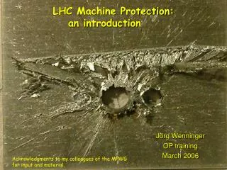
Copper Damage from Fast Beam Loss (R. Shafer) Time to reach thermal stress at front surface – column 3 Estimated time to reach the thermal stress limit at the Bragg peak - column 5 Conclusion Based on these estimates, it is apparent that significant damage can occur in the DTL unless the MPS Fast Protect can shut down the beam in less than about 5 microseconds for beam losses at E<= 7.5 MeV. For the CCL (E>87 MeV), 20 microseconds is adequate. There is no risk of damaging the RF structures during commissioning with single 52-mA, 600-ns long minipulses.
MPS Response Time (Estimate) Fiber speed = 0.65C Copper speed = 0.65C MPS Board delay = 75 nsec
Front End Shut Off Devices • MPS HQA - PPS Only if MPS detects fault • HQA- 65 kV power supply OK • HQA - RFQ Power supply (Interlock) OK, but 5 min. recovery • FPL - 65 kV fast switch OK, 100 msec’s • FPL - RFQ Power supply OK, but 5 min. recovery • FPAR - RFQ RF drive OK, Off, move gate, ON • FPAR - LEBT Chopper Fails unsafe* – BUT Fast • MEBT Chopper Could damage chopper • RF Reference line Long recovery • LEBT Valve Power limit, Not a beam stop • Beam Stop none • +/- 40 kV lens supplies Not 100 % • RF Plasma Source PS Thermal instabilities • RF plasma source gate OK for short time • * PAC 2001 paper, SNS Beam Chopping and its Implications for Machine Protection, L. Doolittle, C. Sibley
Fast Protect – Auto Reset • ALARA – Pulse Width Modulation • Tuning Aid, ALARA • Concentrates Permit Inputs • Inputs Bypassed by Mode • Inhibits carrier link to disable Beam • Inputs: • Loss Monitors • Software trip points, bypass • RF Low level Controls (Maybe latched) • Software maskable • Auto mask sets (Wire Scanner)
Beam Loss Monitors (Saeed’s Talk) • Integration Time – Set in Hardware • Trip point limits – Software adjustable - EPICS • Dose Rate Calibration • Masking Capabilities – Software Masks • Wire Scanner Masks – Auto mask sets for each W.S. • Placement – Near Quadrupoles, Redundant coverage • HV Supply – 1 HV supply takes down every other BLM • Configuration Control • Commissioning vs. Run Periods
Fast Protect - Latched System • Concentrates Permit Inputs • Inhibits carrier link to disable beam • Devices bypassed by Jumper or PLC and Software • Configuration determined on a case by case basis • Inputs Bypassed by machine mode (event link) • System Configuration Control • Equipment maintained in locked racks • Documentation control of changes • System verification after changes
Power supply status NO-Fault signal removed when interlock chain dropped or power supply receives OFF command Valve Status No Fault signal when valve is open and NOT closed (intermediate states are faults) Linac RF Status RF Enabled Signal. Could be auto reset input Target Status Input comes from the target control system. Response should be faster than target shutdown signal. Time Stamp verifies MPS ACTED FIRST Fast Protect - Latched Inputs
Fast Protect – Latched Inputs • Dump Status • Passive Dump Status from PLC • Vacuum Status • Poor integrated vacuum levels • Timing System Status • Ring RF required for IDMP, RING, EDPM, and target modes • Local Oscillator allowed for LDMP, Dplate, and Ion Source modes • PPS Input • PPS search status will latch off beam • Beam Collimator’s • Water cooling • LEBT Chopper • Required for Ring Operation
Loss monitors (Near BCM’s, HIGH QA) Current monitors Integrated current monitors Pulse Width violations Idmp over current monitor HARP Beam current intensity SEM With each HARP Beam Position Monitors Beam off target/dump violation Wire scanners, Faraday cups “Home” Limit switches Fast Protect - Latched Inputs
Beam Loss Accounting system Software integrated loss EPICS Alarm Inputs EPICS Alarms for any PV can trigger latched input on a board level or input signal level. Injection Kickers Power supply status Waveform errors Kicker pair matching Extraction Kickers PS Status Kickers Charged Ring RF Fast Protect - Latched Inputs
Latched Inputs Includes Corrector Power Supplies
MPS Input Bypass Mechanisms • Mode Mask • Global database contains operating mode dependant devices. Devices not required for present mode are masked through hardware. Masks changed with database reconfiguration and IOC reboot. • Jumper / Key / PLC Bypass • Software bypass requires set of closed contacts from a jumper, key, or PLC contacts. • Software Bypass • If hardware configuration allows, input bypassed through software with appropriate EPICS Access Security permissions. • The installation of bypass jumpers will be determined on a case by case basis by committee. Configuration control is monitored by RPS through EPICS.
Wire Scanner (Layered) Protection • Application Requests W.S. Mode, receives “SW KEY” • Run permit won’t allow long pulse until APP releases key • Program crashes, etc. require manual intervention, verification • MODE changed to 10, 50, or 100 usec as appropriate • IOC Receives Request for scan • Motor Record is locked by mode (Allowed by low PW MODE) • MODE == SHORT_PULSE, scan starts • MPS Hardware input masked by MODE (Not software) • Limit switch will cut off beam if not masked by MODE MASK • MODE changes while wire off stops -> Beam cut off • Motor breaks -> Manual intervention required to get wire out of beam
MPS Conclusion • Several layers of protection, Defense in Depth • System is flexible, easy to add / delete sensors as required • Ability to mask through software will increase availability • Easy to run during phased installation. • Hardware enabling SW masks allows configuration control where required, flexibility to mask at will, with same hardware.