NML Machine Protection System (MPS)
180 likes | 312 Vues
NML Machine Protection System (MPS). Arden Warner Fermilab August 2 nd , 2007. Outline. MPS purpose and requirements. How we plan to achieve this. Modes of operation. What signal are needed. Detection hardware. Software system overview. Other issues.

NML Machine Protection System (MPS)
E N D
Presentation Transcript
NML Machine Protection System (MPS) Arden Warner Fermilab August 2nd, 2007
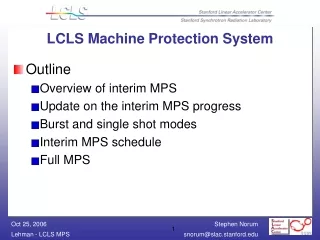
Outline • MPS purpose and requirements. • How we plan to achieve this. • Modes of operation. • What signal are needed. • Detection hardware. • Software system overview. • Other issues
MPS Purpose and Requirements • MPS is being designed to protect the machine from beam induced damage. • Beam hitting machine components. • Invasive beam diagnostics. • Excessive beam loss. • Beam halo or dark current. • Bad Vacuum • Erroneous user input……etc. • MPS is not a personnel protection system (PPS). • Several system will need to provide input that the MPS can use to inhibit or terminate beam on different timescales.
MPS System Requirements • Pre-establish safe conditions for start-up based on the integrity of all preset conditions. • Establish an initial low intensity diagnostic bunch below the threshold for damage. • Transition to full current, then to full rep rate and finally to full number of bunches. • Fast Beam inhibit < 2-3 µs. • Actively compare each beam pulse at 5 Hz. • Monitor steady state operation of the machine. • Monitor long term statistics of the machine. • Be expandable . • Fault and failure analysis. • Fail safe
How do we plan to achieve all this? The MPS systems have to protect the machine from different damage mechanisms resulting in different damage levels at different time scales. • Slow response signals • The slowest reaction time for the system is 200 ms determined by the maximum pulse rep rate of the machine. • OTR Screens • Valves • Power supplies • Fast Signals • Signal that require switching off the beam immediately within a bunch train (< 2-3 µs). Will be dominated by the signal delay from cables and the time of flight from gun to detectors. • Beam loss monitors. • BPMs (transmission measurements). • Fast RF signals • Fast valves • Charge integrity signals
NML Machine parameters The NML accelerator will eventually provide a 1ms long beam pulse at 5 Hz rep rate with a 3 MHz bunch frequency. With the design charge of 3.2 nC this yields currents of 9.5 mA averaged over the bunch train, or a total average current of 50 µA. 1 ms 200ms
How do we plan to achieve all this? • Slower signals can surely be handled by a PLC based interlock system that will be a part of MPS. • Fast signals will be grouped together (logical OR handling) similar to at DESY but grouped in segments according to source type and location to simplify fault analysis. It would be a mistake not to think of fault analysis from the start. • As NML expands the scale of the MPS system will change and will have to accommodate new machine tolerances and parameters so we are carefully thinking about how we distribute detection hardware. Tolerances and therefore concentration of hardware will dictate part of the architecture and logic of the system.
Modes of Operation • In order to systematically achieve the requirements the MPS will operate in several modes based on the operational activity and the beam pulse destination. • Machine Modes – where the beam is supposed to go • Low intensity dump • High intensity dump • Test beam-line • Beam Modes – defines beam type • Diagnostic (pilot beam) • Full beam current • Gun diagnostics
What signals are needed? • Most protection systems start out by either having too many inputs or the wrong inputs. So we are creating a master list of the various systems and we will have to sort them in terms of source, speed and fault level. Some of the obvious inputs are : • RF related signals such as phase, spark detection, LLRF, etc. • Gun parameters– wave plate and pulse control. • Diagnostics– BPMS, Loss monitors etc. • Kicker (fail safe device). • Timing signals. • Keep alive signals. • Vacuum • Movable devices……..
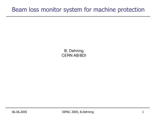
Beam losses and X-ray monitoring • Beam losses will be detected with photo-multipliers attached to plastic scintillator. The placement of the monitors will have to be optimized along the machine. • Response time of detectors ~ 1-2 ns These are used extensively on other MPS systems. Several of these will be tested here in a week or two. Results from DESY with PMT monitors
X-ray monitoring • Sodium Iodide detectors. • Some of this tested already at Mucool and RD (Y. Torun) and will be useful at NML for understanding and monitoring changes in dark current levels. • X-ray monitoring at various energy levels is being done at other locations and we are combining the effort to share the results. Other loss monitor test • Tevatron style loss monitors where tested at A0. • Response ~ 100 µs too slow for fast protection system but may be useful for longer time scale analysis.
Machine Protection System : Software System Overview INTRODUCTION • The purpose of the MPS is to also provide the system with a high level of availability and thus a low number of failures. • Failure is defined as the condition where the beam doesn’t meet the required specifications. There are many levels of failures up the case of no beam being produced. • Faults are defined as anything that produces a failure. Faults can be classified by source, timing, effects, etc • Faults can be resolved into two sources; • Those produced by physics complexity such as un-modeled beam interaction and those produced by component failures i.e. Power Supplies • Faults can be resolved by their timing. • Fast faults happen in the 3MHz range, Medium faults in the 5 Hz range and a range of Slow faults that capture high order beam activity. i.e. integrated beam loss, etc
SYSTEM COMPONENTS • Sensors • Provide measurements of system. • Utilize dedicated processors. • Provide some level of fault tolerance through the use of ATCA compliance. • Examples include BPMs, BLMs, Toroids, etc. • Actuators • Generates some measurable effect on the system. • Utilize dedicated processors. • Provide some level of fault tolerance through ATCA compliance. • Examples include Power Supplies, kickers, scrapers, etc. Permit System Monitors sensors, detects faults and issues beam permits. Operates at different speeds to handle different faults.
SYSTEM COMPONENTS • Data Loggers • Write sensor readings and actuator settings to Data warehouse • Fault Detectors • Monitors permit system, sensors and actuators for faults. • Writes faults to Data Warehouse. • Data Warehouse • Contains sensor readings and actuator settings • Contains tunable parameters • Contains configurations • Contains component failure rates • Contains policies • Contains generic knowledge
SYSTEM COMPONENTS • Configuration Process • Write tunable parameters to permit systems and components with dedicated processors • Handle locking and unlocking of systems and components during parameter update • Fault Predictor • Use component failure rates, faults and knowledge discovery to predict faults • Predicted fault knowledge is used to update tuning parameters to avoid faults. • Knowledge Discoverer • Use sensors and Data Warehouse to find correlations and patterns in Warehouse data. • Utilized a set of automated knowledge discovery tools • Examples of tools include Artificial Neural Networks, Fuzzy sets, etc • This knowledge can be used to predict faults or illuminate areas of system improvement.
SYSTEM COMPONENTS • Policy Maker • Defines global policies and modes of operation. • Policies include whether to relax limits so that the beam lifetime is longer or tighten limits to have a more accurate indicator of faults. • Sanity Checker • Ensures that policies are consistent. • Provides self-check for system fault tolerance i.e. heartbeat, etc. • Finite State Machines • Fsms are hierarchical and operate at many levels. • Applications • Generic suite of user applications.
Other Issues to de addressed • The scale of the system and a time line for each phase of the project. • Documentation • We want to include documentation as part of the design process and have some tools built in for this. • Power failures, glitches and noise. • Some of this is already understood but will include much testing as we progress.