Upgrades for LHC Machine Protection: Addressing Intensity and Energy Challenges
This document discusses the challenges and essential upgrades needed for the Large Hadron Collider (LHC) in terms of machine protection during intensity and energy enhancements. Key issues include the risks associated with increased beam current (up to 1.7 A) and energy levels, specifically focusing on potential damages to the collimators and vacuum system. We explore various scenarios that could lead to accidental damage, the effectiveness of collimators, and how to enhance protection for superconducting magnets during intense operation periods.

Upgrades for LHC Machine Protection: Addressing Intensity and Energy Challenges
E N D
Presentation Transcript
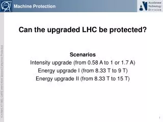
Machine Protection Can the upgraded LHC be protected? Scenarios Intensity upgrade (from 0.58 A to 1 or 1.7 A) Energy upgrade I (from 8.33 T to 9 T) Energy upgrade II (from 8.33 T to 15 T)
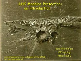
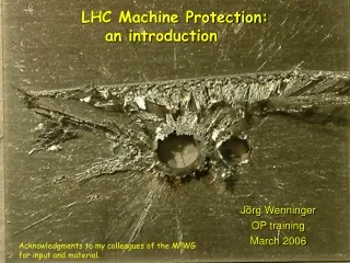
Intensity Upgrade On Monday 25/10/04, during an MD period to test LHC collimator material samples placed in TT40, an extraction fault occurred. Probably due to EMC interference the MSE extraction septa switched off the power converter. As a result, a nominal LHC extraction pulse of 3.4e13p of 450 GeV pierced a hole in the vacuum chamber inside the QTR 4002 and damaged its coils. • This corresponds to 0.061A or 11% of the nominal 0.584 A (respectively 4% of the intended maximum 1.7 A) • The stored energy of a QTR is incomparably small to a typical superconducting magnet. The damage likewise. • How would the beam pipe look after such an incident in LHC? • (Don’t tell me, it can not happen!)
3004, winding short, anticryostat Picture taken from A. Siemko, MTM
Intensity upgrade • Naively speaking, intensity upgrade is an issue of collimation. • The steady intensity, seen by the machine as losses, may not increase beyond the presently set limits. • If the current increases by up to a factor 3 or 4 the collimators have to be effective accordingly. • Note that there is no proof that we will be able to achieve the promised 0.58 A! Hence, any extrapolation includes too many unknowns. • Caveat: The losses do have a time structure, which makes calculations, based on averages, doubtful. • The bunch filling scheme is relevant only for the injection/dump elements (next talk) • Collimator movements • Unknown sources
Time structure of beam losses @HERA Pictures from NIM A 351 (1994), pg 284
Intensity upgrade, summary • The intensity upgrade may be possible, if • everything runs smooth, • the collimators catch all additional losses. • However: • accidental damage is increased, • radiation damage in the warm parts is increased and the machine lifetime reduced (personal dose is correspondingly increased).
Energy Upgrade to 9 T • Moderate energy increase to 7.5 TeV • Assumption: beam current unchanged. • Key issue is now the temperature margin of the magnets. Picture from Stephan Russenschuck
Energy Upgrade to 9 T • Moderate energy increase to 7.5 TeV • Assumption: beam current unchanged. • Key issue is now the temperature margin of the magnets. Picture from LHC Design Report, pg 160
Temperature Margin 4 * more sensitive to beam loss Delta T 0.2 K Joints 0.27 /0.32 K Beam loss 1.12 / 0.28
Moderate Energy Increase • The energy increase to “ultimate” decreases the temperature margin to beam losses (all kind) by a factor 4 • In summary: • The machine will be able to run safely (after some training) • If the losses are further reduced and not modulated • If the losses are spread evenly and mainly in the warm parts of the machine • No energy extraction or quench protection issue
The big step to 15 T • No magnet design yet. • Some rough scaling can be done. • 1. Assumption: The Nb3Sn magnets can absorb there own stored energy (i.e. no energy extraction needed for each individual magnet). • 2. Assumption: No major civil engineering possible (i.e. confined space). • 3. Assumption: Lateral dimensions of the magnets comparable to those of the existing magnets. (At most moderately bigger). • Compared to 8.33 T the stored energy/length has increased by a factor 3.25 @ 15T, assuming the same volume. • Hence the energy density has increased by 3.25, raising the hot spot temperature considerably. • Larger volume seems unavoidable, which increases the stored energy further.
The big step to 15 T • No magnet design yet. • Some rough scaling can be done. • 1. Assumption: The Nb3Sn magnets can absorb there own stored energy (i.e. no energy extraction needed for each individual magnet). • 2. Assumption: No major civil engineering possible (i.e. confined space). • 3. Assumption: Lateral dimensions of the magnets comparable to those of the existing magnets. (At most moderately bigger). • First naïve attempt to protect the magnets: • Quench detection and heaters improved, but essentially as is. • Energy bypass with diodes • Energy extraction with switches and resistors.
Things to be considered • There are no cold diodes above 13 kA. Unlikely that industry is interested to develop radiation tolerant diodes with much higher current, which work as expected at 1.9 K. Note that the only manufacturer of our diodes has discontinued production. It would be difficult to get 13 kA diodes! • The insulation of Nb3Sn coils seems more tricky than that of NbTi coils. The voltage is presumably limited to 1 kV. • Keeping the max current at 13 kA, the inductance has to increase by 3.24 to get to 15 T (same volume). Let’s assume an increase by 4 (very demanding). • The dump resistor is R=Umax/Imax=77mOhm. • Using the same layout as presently the decay time =L/R increases by 4 (as the inductance). • Hence the energy to be absorbed by the diodes increases by 4 and the blocks will have a mass of 4*60 kg =240 kg! Impossible to handle in the tunnel.
Next attempt • Second attempt to protect the magnets: • Quench detection and heaters improved, but essentially as is. • Energy bypass with diodes • Energy extraction with switches and resistors but more often. • Subdivide the sector not in 2 (forth and back) but 8 subdivisions
Normal operation PC Energy extraction
Issues arising from the subdivision • 4 times more 13 kA leads, 4 times more switches, 4 times more resistors • Serious space problem in the tunnel • What about recooling? Water pipes needed! • Consider superconducting (HTS) switching current leads? • In conclusion, the 15 T are quite unhandy -with 64 dump resistors for the dipoles- but feasible, if the current is kept around 13 kA. • We need to invest in solutions to replace the diodes (by HTS switches ?) if higher currents are needed or energy has to be extracted from the magnets. • We need to look into solutions to replace the many bulky switches.
Summary • The beam intensity creates dangerous problems already with the present design. A further increase poses even stronger demands on the collimator system. At higher energies things may be become even worse, if new physics pops up. • A moderate energy increase will be of little use, because the lee-way (temperature margin) decreases dramatically. • A big energy increase is possible (as far as machine protection is concerned), if some commonly known rules are obeyed. However it will be very difficult to fit into the present tunnel. We may need to develop alternatives for the cold diodes (back to the Tevatron solution with HTS switches) and for the very bulky switches (semi- or superconducting). • And finally also the correctors will now need active protection……