Machine Protection and Operational Aspects.
160 likes | 294 Vues
This document outlines the objectives and framework for the newly rejuvenated working group focused on machine protection and operational aspects for the Compact Linear Collider (CLIC). It highlights the need for a thorough analysis of equipment failures, safety concerns, and commissioning strategies essential for efficient machine operation. Key priorities include developing a catalog of potential failures, defining operational cycles, and ensuring preventive maintenance to enhance machine availability. The group's mandate aims to establish a comprehensive machine protection strategy by collaborating with relevant experts and stakeholders.

Machine Protection and Operational Aspects.
E N D
Presentation Transcript
Machine Protection and Operational Aspects. Launching of the working group M.Jonker CTC 20090428
A restart of activity… • Last year a WG and mandate was already presented to the CTC • Due to LHC startup availability of people was not adequate enough. A fresh start… • Mandate (reworked from last year) • Organisation • Priorities • A personal assessment of CLIC MP issues
Mandate Machine protection: • Produce a detailed catalogue of possible equipment failures and their effect on the beam. • Calculate within the present design of elements the time constants between equipment failure and the critical impact on the beam. • Use the above results to determine a strategy of machine protection • Following the above strategy specify the functionality of specific equipment needed for machine protection • In collaboration with the beam instrumentation experts produce a concept for beam loss monitoring of the individual beams Safety: • Review all safety issues which could possibly affect CLIC operation Commissioning Strategies • Elaborate and Document • what type of beams will be needed • will commissioning of subsystems be possible during construction, impact on security and shielding • possible scenario for energy staging Operational availability • Elaborate and document the operational cycle of the fully commissioned CLIC machine and calculate an overall efficiency figure for the machine. • Preventive maintenance on RF structures/klystrons for drive beams, Sources, Passive alignement, Calibration of BI/alignment/stabilization equipment, re-optimization of the working point of the stabilization system…Note: certain technologies used for CLIC are so much pushed to the technological limits that regularly scheduled interventions may be needed to ensure the operational state. • Down-times due to equipment failures (i.e. specification of the MTBF and MTTR of various equipment) • Others Contribution to CLIC cost estimate
Composition of WG: Michel Jonker (Chairman) Django Manglunki Stefano Raedelli (for few individual sessions and topics) Ruediger Schmitt (for individual sessions and topics) Barbara Holzer/Bernd Dehning (tbd, one of them) Frank Tecker: confirmed? Jan Uythoven: to be confirmed Thomas Otto: contacted; interested Project/scientific associate in BE-BI: in preparation Tom Shea, presently ORNL/SNS for one year as scientific associate RF person ? (breakdown effects, RF structure damage) Others (TBD) Reporting line: to CTC
Restart of activity… In practice: • Contact WG members, organize first meeting. • Present outline to the ACE meeting in May Machine protection and operational aspects, what can be done before the CDR in 2010. • Present an action plan of the Working group in June Highest priority is Machine Protection, followed by expected unavailability due to machine failures and recovery.
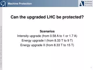
CLIC Machine Protection A personal assessment of the issues of the CLIC machine protections (exercise prior to accepting WG chairmanship) • An extensive topic: • Many different accelerator component types (linacs, combiner rings, transport lines, decelerator, damping rings, main linac, beam delivery and diagnostics system, post beam line). • Many different beams with different characteristics (energy intensity, brilliance) • Impressive beam power?
Beams and beam power CLIC drive beam (2.4 GeV) bunch train pulse second Bunches 1 2922 7 0128 3 506 400 Charge [nC ] 8.4 24 544 58 9075 29 453 760 Time [ns] 0.083 244 140 300 1 s Current [A] 100 100 4.20 0.029 Beam Energy [kJ] 0.020 59 1 413 70 689 CLIC main beam bunch pulse second Bunches 1 312 15600 Charge [nC ] 0.60 186 9285 Time [ns] 0.5 156 1 s Current [A] 1.2 1.2 9.3 10-6 Beam Energy @2.4 GeV [kJ] 0.0014 0.45 22.3 Beam Energy @9 GeV [kJ] 0.0053 1.69 83.6 Beam Energy @1.5 TeV [kJ] 0.89 278 13927 LEP (100 GeV) bunch beam total Bunches 1 8 16 Current [mA] 600 5000 10000 Charge [nC ] 53.4 445 890 Beam Energy [KJ] 5.4 45 90
Effect of beam in matter Material C Al Cu W Click Drive Train (2.4 GeV, 24545 nC) Energy Density @ shower core [J g-1] 1.34 3.08 40 187 Energy Density IB @ 1 mm2 [J g-1] 4293 3964 34442810 Energy Density EIB @ 1 cm2 [J g-1] 43 40 34 28 Click Main Pulse (2.4 GeV, 204 nC) Energy Density @ shower core [J g-1] 0.01 0.03 0.34 1.57 Energy Density IB @ 14 mm2 [J g-1] 2.6 106 2.4 1062.0 1061.7 106 Energy Density EIB @ 1 mm2 [J g-1] 36 33 29 23 Click Main Pulse (1.5 TeV, 186 nC) Energy Density @ shower core [J g-1] 3.41 9.12 122.37 614.43 Energy Density IB @ 5.7 mm2[J g-1] 5.7 106 5.3 1064.6 1063.7 106 Energy Density EIB @ 1 mm2 [J g-1] 32 30 26 21 Lep Beam (100GeV, 445 nC) Energy Density @ shower core [J g-1] 0.64 1.68 22 112 Energy Density IB @ 0.1 mm2 [J g-1] 778 719 624 510 Energy Density IB @ 1 mm2 [J g-1] 78 72 62 51 Note: in energy density in cupper for Melting : 400 J g-1, Structural yield 62 J g-1
Beam induced damage • Damage to machine structures primarily due to the large charge density. • Small beam size for main beam • High current for drive beam However, total beam power makes proper disposal of the main beam more challenging.
Two type of failures • Failures causing slow onset of losses • Magnet system • Vacuum system • Failures causing fast losses • RF breakdown • Kicker misfiring • Klystron trips
Protection against slow losses Avoid slow losses by choosing magnet current circuits with a large time constant: • A power converter commit to stay within an acceptable tolerance for the next 2 ms. • We have time to abort the next pulse in case of failures of a magnet power converter. If so, magnet failures should not be an issue. Similar: A 2 ms closure-inhibit time window for fast sector valves of the vacuum system?
Protection against fast losses- Oops, we are loosing the main beam, can we still dump it? • Fast loss detection and fast dump may catch the tail of the pulse. • For the head of the pulse, we must rely on passive protection. Can the passive protection also be robust enough such that we do not need a fast dump? Note: many processes that causes a loss of the main beam will most likely already spoil its brilliance.
Beam permits Beam permits Local MP Supervisor Local MP Supervisor Interlocks Interlocks Interlocks Interlocks Interlocks Interlocks Local abort Local abort Local abort Local abort Local abort Local abort Beam permits Beam permits Beam permits Beam permits Beam permits Beam permits Beam permits Beam permits Local MP Supervisor Local MP Supervisor Beam permits Beam permits Beam permits Beam permits Local MP Supervisor Local MP Supervisor Beam permits Beam permits Beam permits Beam permits Master MP Supervisor Network for diagnostics and control hw architecture of MP logic • A central MP supervisor controls 4 parallel Beam-Permit-Chains (BPC) for the two drive and two main beams. • Each Beam permit chain carries the beam permits for different beam types (pilot, tests, nominal). • A Beam-Permit-Chain contains n local nodes with user permit inputs that will inhibit the beam permit chain (in both directions). • In case the beam permit chain is interrupted, the local node will also provide signals that can be used by local beam and equipment abort systems.
Principle of next pulse permit: • If a successful pulse have been delivered, (confirmed by post pulse analysis of previous pulse) • if no power converter failure (fault, tolerance error, di/dt) was detected since the last pulse The machine will be ready for the next pulse. Otherwise, successive test beams of lower intensity, and emmittance will have to used to re-establish the readiness of the machine.
Machine Protection Study Topics • Catalogue all possible fault scenarios; estimate their incidence rate and the damage incurred by these faults (financial, operational). Develop protection strategies that can limit the incidence rate and/or damage to a level where the risk is acceptable. • Study material damage and limits on beam loss/size, including damage by direct high density beam passage, damage by fully developed showers, damage from synchrotron radiation, damage by induced heating (wakefield). • Study required stabilities for all power converters • Study failsafe powering circuits. A powering circuit is failsafe if it can commit to a specified current within the tolerance for the coming n ms. Study early fault detection by power converters (missing phase, thyristors or FET non firing), integrated dI/dt detection. • Study RF failure scenario’s and their impacts • Study rt-schemes to dispose of dangerous beams in case of fast failure scenario’s, fast kickers, fast quadrupole kickers, fast beam diluters, laser systems. Possibly in combination with permanent non-linear protection systems. • Establish beam permit validation procedure based on progressive tests with safe beam. • Define safe beam conditions (charge density, total charge and energy, see point 1).
Conclusion • Very interesting • I am eager to get the process going.