CLIC Machine Protection
CLIC Machine Protection. Main Beam 2 injectors e + e - 1 Linac , 2.66 GeV , 234 m ?, 2 GHz 2 Pre-damping rings 398 m NB: Synchrotron power from damping rings: 3.857 Mev turn -1 x 204 nC /1.2 ms turn -1 = 656 KW, (13 KJ pulse -1 ). 2 Damping rings 493 m (same as PDR)

CLIC Machine Protection
E N D
Presentation Transcript
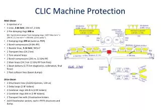
CLIC Machine Protection Main Beam • 2 injectors e+ e- • 1 Linac, 2.66 GeV, 234 m?, 2 GHz • 2 Pre-damping rings 398 m NB: Synchrotron power from damping rings: 3.857 Mev turn-1 x 204 nC /1.2 ms turn-1 = 656 KW, (13 KJ pulse-1). • 2 Damping rings493 m(same as PDR) • 2 Bunch compressors (4 GHz RF) • 1 Booster linac,5.14GeV, 561m? • 2 Transport lines (24.2 km) • 2 Turn around loops • 2 Bunch compressors (245 m, 12 GHz RF) • 2 Main linacs (24.2 km 12 GHz RF from Pets) • 2 Beam delivery (2.75 km diagnostics, collimation, final focus) • 2 Post collision lines (beam dumps) Drive Beam • 2 Drive beam linac (2x326 klystrons, 139 us) • 2 Delay loops (2 RF kickers) • 2 Combiner rings 144.8 m (2 RF kickers) • 2 Combiner rings 434 m (2 RF kickers) • 2 Transport line with 24 extraction kickers • 2x24 Decelerator sectors, each n PETS structures and dump.
QUAD QUAD POWER EXTRACTION STRUCTURE ACCELERATING STRUCTURES BPM CLIC – basic features • High acceleration gradient • “Compact” collider – total length < 50 km • Normal conducting acceleration structures • High acceleration frequency (12 GHz) • Two-Beam Acceleration Scheme • High charge Drive Beam (low energy) • Low charge Main Beam (high collision energy) • Simple tunnel, no active elements • Modular, easy energy upgrade in stages CLIC TUNNEL CROSS-SECTION 4.5 m diameter Drive beam - 101 A, 240 ns from 2.4 GeV to 240 MeV 12 GHz – 140 MW Main beam – 1 A, 156 ns from 9 GeV to 1.5 TeV
326 klystrons33 MW, 139 ms combiner rings Circumferences delay loop 72.4 mCR1 144.8 mCR2 434.3 m drive beam accelerator2.38 GeV, 1.0 GHz CR1 CR1 1 km Delayloop CR2 CLIC – overall layout 326 klystrons33 MW, 139 ms drive beam accelerator2.38 GeV, 1.0 GHz Drive Beam Generation Complex 1 km Delayloop CR2 klystrons will probablychange to ~10 MW decelerator, 24 sectors of 878 m Drive beam BDS2.75 km BDS2.75 km BC2 BC2 245m 245m IP e+ main linac e- main linac , 12 GHz, 100 MV/m, 21.1 km TAR=120m TAR=120m 48.4 km Main beam CLIC 3 TeV booster linac, 9 GeV BC1 e- injector2.86 GeV e+ injector, 2.86 GeV e-PDR398m e-DR493m Main Beam Generation Complex e+PDR398m e+DR493m
326 klystrons 33 MW, 29 ms combiner rings Circumferences delay loop 80.3 m CR1 160.6 m CR2 481.8 m drive beam accelerator 2.47 GeV, 1.0 GHz CR1 CR1 1 km delay loop CR2 CLIC Layout for 0.5 TeV 326 klystrons 33 MW, 29 ms drive beam accelerator 2.47 GeV, 1.0 GHz 1 km delay loop Drive Beam Generation Complex CR2 decelerator, 5 sectorsof 878 m BDS 1.87 km BDS 1.87 km BC2 BC2 245m 245m IP1 e- main linac , 12 GHz, 80 MV/m, 4.39 km e+ main linac TA R=120m TA R=120m 13.0 km CLIC overall layout 0.5 TeV booster linac, 9 GeV, 4 GHz Main Beam Generation Complex BC1 e- injector 2.86 GeV e+ injector, 2.86 GeV e+ DR 493m e- DR 493m
~20 km CLIC Layout at various energies Linac 1 I.P. Linac 2 0.5 TeV Stage Injector Complex 4 km 4 km ~13 km 1 TeV Stage Linac 1 I.P. Linac 2 Injector Complex 7.0 km 7.0 km 3 TeV Stage Linac 1 I.P. Linac 2 Injector Complex 21.1 km 2.75 km 2.75 km 21.1 km 48.4 km
CLIC Parameters and upgrade scenariohttp://cdsweb.cern.ch/record/1132079/files/CERN-OPEN-2008-021.pdf 4th phase: 3 TeV luminosity upgrade 3 TeV nominal parameters 2nd phase: 500 GeV luminosity upgrade 500 GeV nominal parameters 3rd phase: 0.5 to 3 TeV energy upgrade 3 TeV conservative parameters 1rst phase: Initial operation 500 GeV conservative parameters J-P.Delahaye
326 klystrons33 MW, 139 ms combiner rings Circumferences delay loop 72.4 mCR1 144.8 mCR2 434.3 m drive beam accelerator2.38 GeV, 1.0 GHz CR1 CR1 1 km Delayloop CR2 CLIC – overall layout 326 klystrons33 MW, 139 ms drive beam accelerator2.38 GeV, 1.0 GHz Drive Beam Generation Complex 1 km Delayloop CR2 decelerator, 24 sectors of 878 m Drive beam BDS 2.75 km BDS 2.75 km BC2 BC2 245m 245m IP e+ main linac e- main linac , 12 GHz, 100 MV/m, 21.1 km TA R=120m TA R=120m 48.4 km Main beam CLIC 3 TeV booster linac, 9 GeV BC1 e- injector2.86 GeV e+ injector, 2.86 GeV e-PDR398m e-DR493m Main Beam Generation Complex e+PDR398m e+DR493m
2 1 3 Two-beam acceleration Counter propagation from central complex Instead of using a single drive beam pulse for the whole main linac, several (NS = 24) short ones are used. Each one feed a ~800 m long sector of TBA. decelerator sector main linac main beampulse pulse 2 pulse 1 From central complex (DLDS-like system) Counter-flow distribution allows to power different sectors of the main linac with different time bins of a single long electron pulse. The distance between pulses is 2 LS = 2 Lmain/NS. The initial drive beam pulse length is equal to 2 Lmain= 140 ms/c. R.Corsini
CR1 Drive Beam decelerator, 24 sectors of 876 m 2904 bunches83 ps (12 GHz) Main Beam 240 ns 140ms, 24 trains 5.8ms Drive beam generation summary Drive beam structure - final 326 klystrons33 MW, 139 ms Bunch charge: 8.4 nC, Current in train: 100 A drive beam accelerator2.38 GeV, 1.0 GHz 1 km 240 ns initial 240 ns Delayloop CR2 5.8 ms 140 ms train length - 24 24 sub-pulses 4.2 A - 2.4 GeV – 60 cm between bunches 24 pulses – 101 A – 2.5 cm between bunches
Drive beam generation basics • Efficient acceleration • Frequency multiplication No RF to load RF in Full beam-loading acceleration in traveling wave sections High beam current Most of RF power to the beam “short” structure - low Ohmic losses Beam combination/separation by transverse RF deflectors
Fully loaded operation • efficient power transfer from RF to the beam needed “Standard” situation: • small beam loading • power at structure exit lost in load “Efficient” situation: high beam current high beam loading no power flows into load VACC≈ 1/2 Vunloaded
Transient DP/P (%) -5 0 5 Steady state Time resolved beam energy spectrum measurement in CTF3 100 200 300 400 Time (ns) Fully loaded operation • Disadvantage: any current variation changes energy gainat full loading, 1% current variation = 1% voltage variation • Requires high current stability • Energy transient(first bunches see full field) • Requires continuous bunch train E0 Ebeam steady state E0 /2 tfill t
Delay Loop Principle double repetition frequency and current parts of bunch train delayed in loop RF deflector combines the bunches (fdefl=bunch rep. frequency) Path length corresponds to beam sub-pulse length
injection line 1st turn 2nd septum 1st deflector 2nd deflector local inner orbits lo RF deflector field 4rd 3rd lo/4 RF injection in combiner ring combination factors up to 5 reachable in a ring Cring = (n + ¼) l Cringhas to correspond to the distance of pulses from the previous combination stage!
Lemmings Drive Beam AlexandraAndersson
Drive Beam time structure = 3 * LCR1 = 2 * LDL C.Biscari
Drive Beam CTF3 - CLIC • Still considerable extrapolation to CLIC parameters • Especially total beam power (loss management, machine protection) • Good understanding of CTF3 and benchmarking needed
326 klystrons33 MW, 139 ms combiner rings Circumferences delay loop 72.4 mCR1 144.8 mCR2 434.3 m drive beam accelerator2.38 GeV, 1.0 GHz CR1 CR1 1 km Delayloop CR2 CLIC – power generation 326 klystrons33 MW, 139 ms drive beam accelerator2.38 GeV, 1.0 GHz Drive Beam Generation Complex 1 km Delayloop CR2 decelerator, 24 sectors of 878 m Drive beam BDS 2.75 km BDS 2.75 km BC2 BC2 245m 245m IP e+ main linac e- main linac , 12 GHz, 100 MV/m, 21.1 km TA R=120m TA R=120m 48.4 km Main beam CLIC 3 TeV booster linac, 9 GeV BC1 e- injector2.86 GeV e+ injector, 2.86 GeV e-PDR398m e-DR493m Main Beam Generation Complex e+PDR398m e+DR493m
Power extraction structure PETS • must extract efficiently >100MW power from high current drive beam • passive microwave device in which bunches of the drive beam interact with the impedance of the periodically loaded waveguide and generate RF power • periodically corrugated structure with low impedance (big a/λ) • ON/OFFmechanism The power produced by the bunched (0) beam in a constant impedance structure: Design input parameters PETS design Beam eye view P – RF power, determined by the accelerating structure needs and the module layout.I – Drive beam currentL – Active length of the PETSFb – single bunch form factor (≈ 1)
Power Extraction Structure (PETS) PETS parameters: • Aperture = 23 mm • Period = 6.253 mm (900/cell) • Iris thickness = 2 mm • R/Q = 2258 Ω • V group= 0.453 • Q = 7200 • P/C = 13.4 • E surf. (135 MW)= 56 MV/m • H surf. (135 MW) = 0.08 MA/m (ΔT max (240 ns, Cu) = 1.8 C0) The PETS comprises eight octants separated by the damping slots. Each of the slots is equipped with HOM damping loads. This arrangement follows the need to provide strong damping of the transverse modes. H-field E-field To reduce the surface field concentration in the presence of the damping slot, the special profiling of the iris was adopted. I. Syratchev
Field development in a PETS The induced fields travel along the PETS structure and build up resonantly (here only dipole fields in animation) Courtesy of SLAC and I.Syratchev
CLIC two-beam Module layout Standard module Total per module8 accelerating structures8 wakefield monitors4 PETS2 DB quadrupoles2 DB BPMTotal per linac8374 standard modules Other modules have 2,4,6 or 8 acc.structures replaced by a quadrupole(depending on main beam optics) Total 10462 modules, 71406 acc. structures, 35703 PETS G.Riddone
CLIC two-beam Module Transfer lines Drive Beam Main Beam Alignment system, beam instrumentation, cooling integrated in design G.Riddone
326 klystrons33 MW, 139 ms combiner rings Circumferences delay loop 72.4 mCR1 144.8 mCR2 434.3 m drive beam accelerator2.38 GeV, 1.0 GHz CR1 CR1 1 km Delayloop CR2 CLIC – main beam generation 326 klystrons33 MW, 139 ms drive beam accelerator2.38 GeV, 1.0 GHz Drive Beam Generation Complex 1 km Delayloop CR2 decelerator, 24 sectors of 878 m Drive beam BDS 2.75 km BDS 2.75 km BC2 BC2 245m 245m IP e+ main linac e- main linac , 12 GHz, 100 MV/m, 21.1 km TA R=120m TA R=120m 48.4 km Main beam CLIC 3 TeV booster linac, 9 GeV BC1 e- injector2.86 GeV e+ injector, 2.86 GeV e-PDR398m e-DR493m Main Beam Generation Complex e+PDR398m e+DR493m
Main beam Injector Complex e- Main Linac e+ Main Linac e- BC2 e+ BC2 12 GHz 12 GHz 8 GeV 48 km 3 TeV Base line configuration Booster Linac 5.14 GeV 4 GHz e+ BC1 4 GHz e- BC1 4 GHz 2.86 GeV e+DR 493m 2.86 GeV e-DR 493m e-PDR 398m e+PDR 398m 2.86 GeV 2.86 GeV Injector Linac 2.66 GeV 2 GHz e-/g Target g/e+ Target Pre-injector Linac for e+ 200 MeV Laser Primary beam Linacfor e- 5 GeV Pre-injector Linac for e- 200 MeV DC gun Polarized e- 2 GHz 2 GHz e- gun AMD 2 GHz
PDRparameters F. Antoniou, et al., 2009
CLIC damping ring layout 125m 39m 125m
New DR parameters (2009) • New DR increased circumference by 30% and energy by 20% • DA significantly increased • Magnet strength reduced to reasonable levels (magnet models already studied) • Combined function bend increases significantly vertical beta on dipoles • TME optics modification and energy increase reduces IBS growth factor to 2 (as compared to 5.4) • Ready for CDR • Further optimization with respect to IBS (F. Antoniou PhD thesis)
Synchrotron radiation absorption K. Zolotarev, et al., 2008 Regular absorbers of 26kW for PETRA-III project
BINP PM wiggler BINP SC wiggler ANKA SC wiggler Wigglers’ effect with IBS • Super-conducting magnets have to be designed, built and tested • Two wiggler prototypes • 2.5T, 5cm period, NbTi coil, built by BINP • 2.8T, 4cm period, Nb3Sncoil, built by CERN/ANKA • Aperture fixed by radiation absorption scheme Stronger wiggler fields and shorter wavelengths necessary to reach target emittance due to strong IBS With super-conducting wigglers, the achieved normalized horizontal emittance drops below 400nm
Beam Delivery System • diagnostics, emittance measurement, energy measurement, … • collimation, crab cavities, beam-beam feedback, beam extraction,beam dump
Collimator (Be) survival • Energy Collimators designed to survive a full pulse • Temperature raise after impact of a full train below melting level.
KonradElsener, CLIC meeting, 15 May 2009 Post-Collision line CLIC conceptual design 3 TeV (20 mrad crossing angle) A. Ferrari et al., PRSTA&B 12 021001 (2009) stretched lattice, as proposed at ’08 CLIC - ACE NEW ! Side View
Documentation • General documentation about the CLIC study: http://cern.ch/CLIC-Study/ • CLIC scheme description:http://preprints.cern.ch/yellowrep/2000/2000-008/p1.pdf • CLIC Physics http://clicphysics.web.cern.ch/CLICphysics/ • CLIC Test Facility: CTF3 http://ctf3.home.cern.ch/ctf3/CTFindex.htm • CLIC technological challenges (CERN Academic Training)http://indico.cern.ch/conferenceDisplay.py?confId=a057972 • CLIC Workshop 2008 (most actual information) http://cern.ch/CLIC08 • EDMShttp://edms.cern.ch/nav/CERN-0000060014 • CLIC ACE (advisory committee meeting)http://indico.cern.ch/conferenceDisplay.py?confId=58072 • CLIC meeting (parameter table) http://cern.ch/clic-meeting • CLIC parameter notehttp://cern.ch/tecker/par2007.pdf • CLIC notes http://cdsweb.cern.ch/collection/CLIC%20Notes • CLIC PBS https://edms.cern.ch/file/918792/5/CLIC_PBS_3_TeV_CDR.xlsx • CDR layout (with responsibles)http://indico.cern.ch/getFile.py/access?contribId=43&resId=8&materialId=0&confId=58072