P11011: Motion-Tracking System Final Design Review
180 likes | 324 Vues
P11011: Motion-Tracking System Final Design Review. Brittany Bochette Lindsey Clark Mike Ostertag Maya Ramaswamy Andrei Stihi. Project Background. Motion-tracking system that measures knee flexion and head-tilt Continuation of past senior design groups P10010 Sensors

P11011: Motion-Tracking System Final Design Review
E N D
Presentation Transcript
P11011: Motion-Tracking SystemFinal Design Review Brittany Bochette Lindsey Clark Mike Ostertag Maya Ramaswamy Andrei Stihi
Project Background • Motion-tracking system that measures knee flexion and head-tilt • Continuation of past senior design groups • P10010 Sensors • P10011 Attachment Methods • Customers are Nazareth Physical Therapy Clinic and Rochester General Hospital
Key Customer Needs • Measurement • +/- 80 degrees of tilt and +/- 100 degrees of rotation • Accuracy • 5-10 degrees error • Reproducibility • 5-10 degrees • Speed of Attachment and Removal • 2 minutes, 5 seconds
Concept Overview USB FTDI 3.3V Breakout Board Brass screws Attachment Snaps Razor 9DOF IMU Protective enclosure Foam stabilizer
System Architecture Base Unit Knee Flexion USB Head-Tilt Options Quit
Attachment Methods Head attachment and enclosure Leg attachments with enclosures
Enclosures • Brass screws and nuts were used, along with rubber washers for interference free operation • Foam padding was used on the backside to stabilize it when used with various attachment methods through the use of snaps Internals:
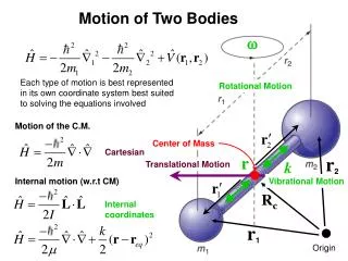
Determining Knee Flexion • Sensor is placed on the side of the leg with gravity being felt in the X and Y components of the accelerometer • The orientation of the sensor relative to gravity was calculated with Equation 1. • The amount of flexion is the difference between the two angles as seen in Equation 2. Eq. 1 Eq. 2 Y Z X Ag
Determining Head Orientation • Head has complex motion due to three-axes of rotation • Breaking down motion to three individual axes (seen above) simplifies the process of determining orientation Anterocollis Retrocollis Laterocollis Torticollis
Determining Head Orientation • Antero/retrocollis (pitch) and laterocollis (roll) were determined using a three-axis accelerometer • Angles were determined by comparing the components of acceleration caused by gravity (Ag) • Eq. 3 • Eq. 4 Z X Y Ag
Determining Head Orientation • Torticollis (yaw) was determined using the three-axis magnetometer and the following procedure: • The magnetometer readings were corrected for tilt based upon the pitch and roll found previously. • A current magnetic heading was found with the following equation: • The difference between the initial and current magnetic heading is the amount that the head has rotated. Eq. 5 Eq. 6
Testing • 30˚ rotation in the pitch, roll, and yaw directions • Changes in degree during four knee flexion cycles
Current State of Design • Design is functional • Meets all engineering specifications except • Measurement of shift –discussed this with the customer and it is an option for future designs • Budget requirements - $1000 allowed, $735.76 spent • After changing scope, we used the more expensive Razor IMU for both systems • This caused a slight budget overrun for the knee device • On schedule with exception of rescheduled D3 meetings
Risk Assessment • Contacting our customers and scheduling meetings with them proved to be one of the most relevant risks. • The device not meeting customer needs was also something that was a possible risk up until week nine. • Not being able to communicate with the base unit was another risk we had to address
Project Evaluation • Project was originally scoped too large • The intent of the project became clearer after a re-scoping at the end of MSD I • Base unit and sensor sub-systems should be one group • With a similar project, a prototype should be the first step rather than a fully functioning system
Recommendations • Being able to measure shift of the head would be something desired by Dr. Barbano in the future. • Dr. Barbano also voiced a need to have something on the device that helped him to level the device on the patient so that human error was reduced or even eliminated. • Dr. Mowder suggested using Dysom or some other rubber-like material to prevent the strap on the calf from slipping