Download
1 / 33
360 likes | 612 Vues
LEARNING GOALS. Study the basic types of two-port models. Admittance parameters Impedance parameters Hybrid parameters Transmission parameters. Understand how to convert one model into another. TWO-PORT NETWORKS. In many situations one is not interested in the internal organization of a

E N D
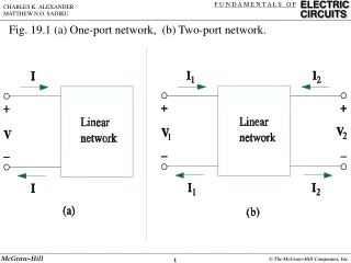
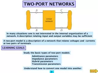
LEARNING GOALS Study the basic types of two-port models Admittance parameters Impedance parameters Hybrid parameters Transmission parameters Understand how to convert one model into another TWO-PORT NETWORKS In many situations one is not interested in the internal organization of a network. A description relating input and output variables may be sufficient A two-port model is a description of a network that relates voltages and currents at two pairs of terminals
The computation of the parameters follows directly from the definition ADMITTANCE PARAMETERS The network contains NO independent sources The admittance parameters describe the currents in terms of the voltages The first subindex identifies the output port. The second the input port.
Find the admittance parameters for the network LEARNING EXAMPLE Next we show one use of this model
An application of the admittance parameters Determine the current through the 4 Ohm resistor The model plus the conditions at the ports are sufficient to determine the other variables.
LEARNING EXTENSION Find the admittance (Y) parameters
Use the admittance (Y) parameters to find the current Io LEARNING EXTENSION Conditions at I/O ports Replace in model Solve for variable of interest
The ‘z parameters’ can be derived in a manner similar to the Y parameters IMPEDANCE PARAMETERS The network contains NO independent sources
rearranging LEARNING EXAMPLE Find the Z parameters Write the loop equations
LEARNING EXAMPLE Use the Z parameters to find the current through the 4 Ohm resistor Output port constraint Input port constraint
LEARNING EXTENSION Find the Z parameters. Find the current on a 4 Ohm load with a 24V input source
HYBRID PARAMETERS The network contains NO independent sources These parameters are very common in modeling transistors
Find the hybrid parameters for this circuit LEARNING EXAMPLE Non-inverting amplifier Equivalent linear circuit
LEARNING EXTENSION Find the hybrid parameters for the network
Verification Determine the input impedance of the two-port LEARNING EXTENSION
TRANSMISSION PARAMETERS ABCD parameters The network contains NO independent sources
LEARNING EXAMPLE Determine the transmission parameters
LEARNING EXTENSION Determine the transmission parameters
PARAMETER CONVERSIONS If all parameters exist, they can be related by conventional algebraic manipulations. As an example consider the relationship between Z and Y parameters
SERIES: Currents are the same. Voltage of interconnection is the sum of voltages CASCADE: Output of first subsystem acts as input for the second INTERCONNECTION OF TWO-PORTS Interconnections permit the description of complex systems in terms of simpler components or subsystems The basic interconnections to be considered are: parallel, series and cascade PARALLEL: Voltages are the same. Current of interconnection is the sum of currents The rules used to derive models for interconnection assume that each subsystem behaves in the same manner before and after the interconnection
SERIES: Currents are the same. Voltage of interconnection is the sum of voltages Series interconnection using Z parameters
CASCADE: Output of first subsystem acts as input for the second Cascade connection using transmission parameters Matrix multiplication does not commute. Order of the interconnection is important
Find the Y parameters for the network LEARNING EXAMPLE
Find the Y parameters for the network using a direct approach
Network A Network B Find the Z parameters of the network LEARNING EXAMPLE Use direct method, or given the Y parameters transform to Z … or decompose the network in a series connection of simpler networks
LEARNING EXAMPLE Find the transmission parameters By splitting the 2-Ohm resistor, the network can be viewed as the cascade connection of two identical networks
Given the demand at the receiving end, determine the conditions on the sending end Transmission parameters are best suited for this application Power factor angle LEARNING by APPLICATION In the next slide we show how to determine the transmission parameters for the line. Here we assume them known and use them for analysis
Using the hybrid parameters Effect of load resistance Determine the effect of the load on the voltage gain LEARNING EXAMPLE Hybrid parameters are computed in next slide
Computing the hybrid parameters for non-inverting amplifier (repeat earlier example) Non-inverting amplifier Equivalent linear circuit
Gain required = 10,000 on a load of 1kOhm LEARNING BY DESIGN For the final solution we will need to cascade amplifiers. Hence the transmission parameters will prove very useful Analysis of solution: -Even with infinite load the maximum gain is only 6,667 Likely causes: -R2 is higher than input resistance Ri -Desired gain is comparable to the maximum gain, A, of the Op-Amp Proposed solution: -Cascade two stages, each with ideal gain of 100. This also lowers R2 to 99kOhm
Effect of load resistance. G=10,000 Identical stages Two-Ports Analysis of proposed solution Since the two stages will be cascaded, the transmission parameters of the proposed solution will be